Course Manual
Setting up the System
-
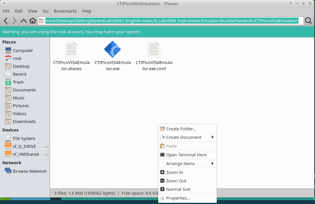
If you are using the Emulator, load it by navigating to /root/Desktop/GettingStartedLabVIEW1-English-main/3) LabVIEW Instrument Emulator/builds/HandsOn/CTIPicoVISAEmulator/
-
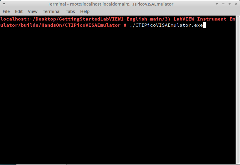
Right-click in the window and select Open Terminal Here
-
Type in./CTIPicoVISAEmulator.exe
-
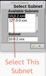
The emulator will ask you to select a subnet.
-
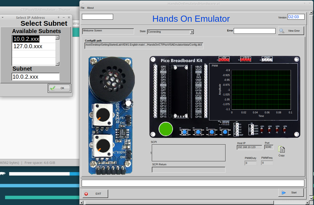
It will then sit waiting for a connection. “Connecting” will be displayed in status bar.
Lesson 1 – LabVIEW “Hello World” LED On/Off
Optional: Setting up the Hardware
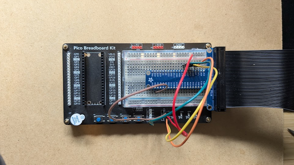
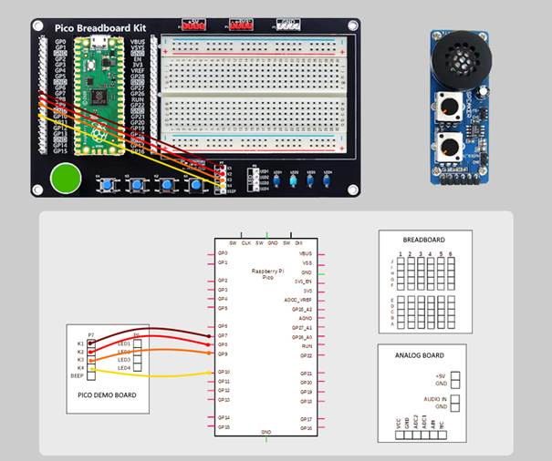
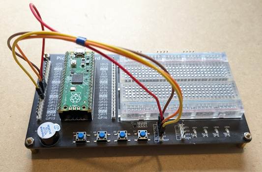
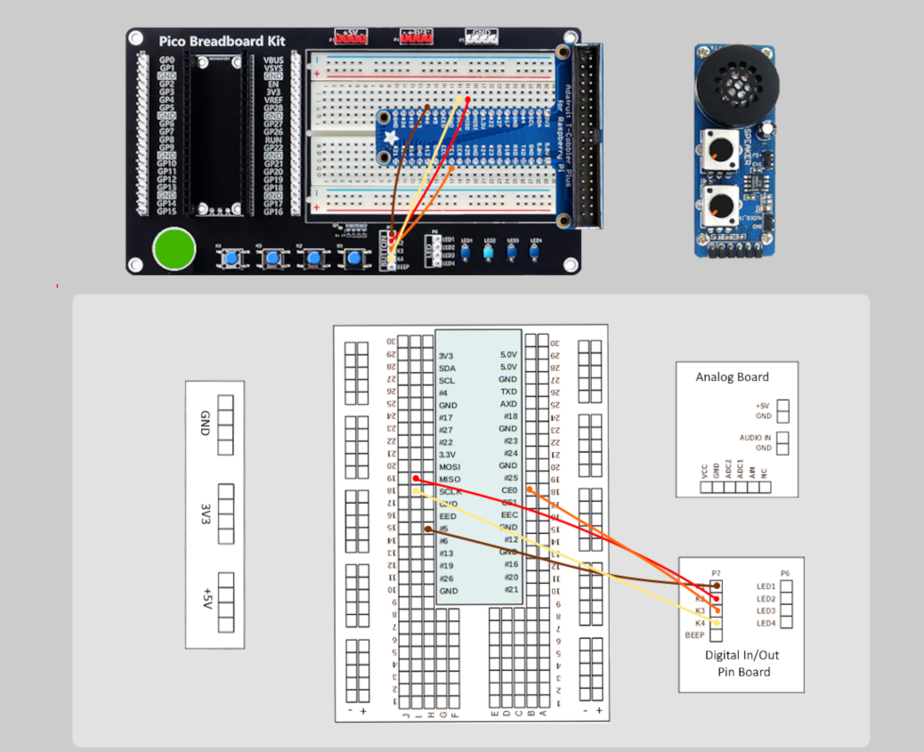
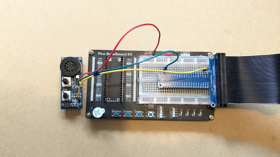
Setting up the Pico Hardware
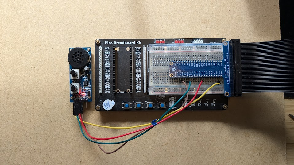
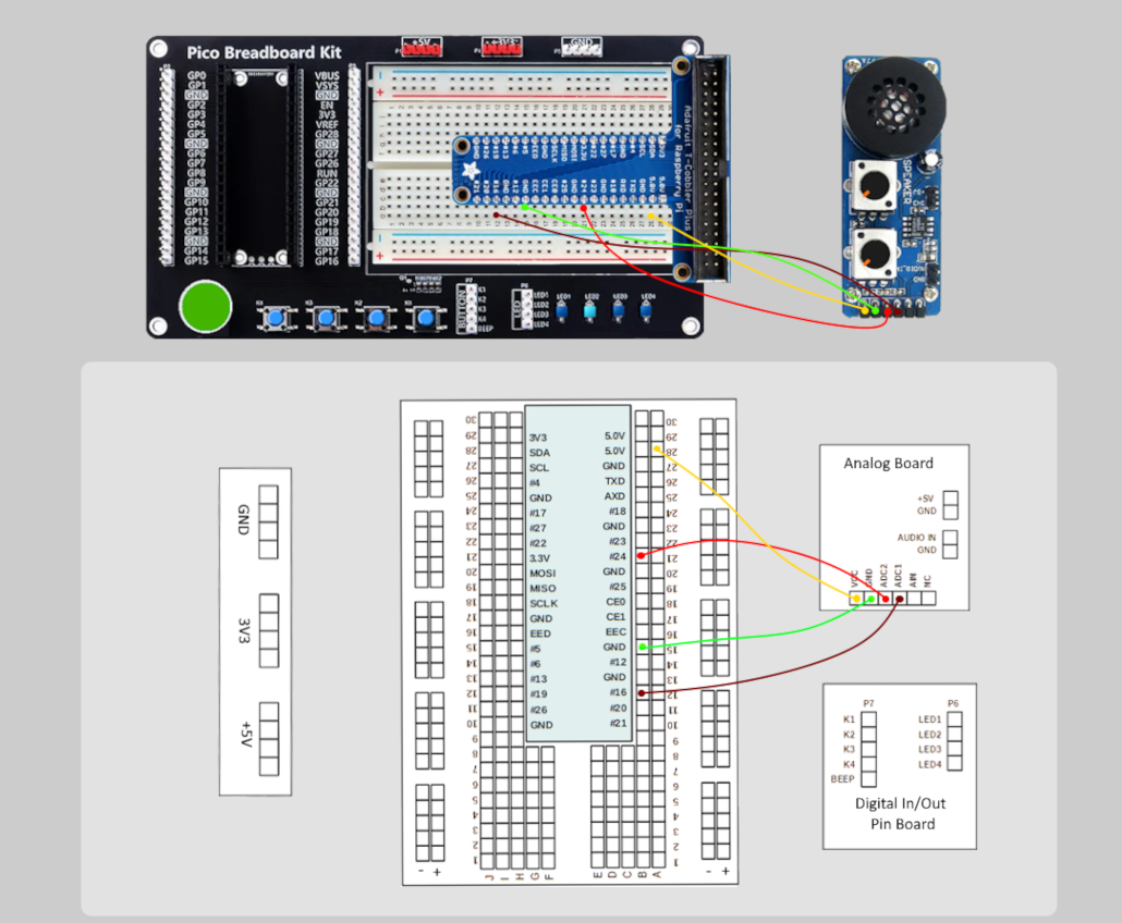
Wire your Pico Hardware to match the images below
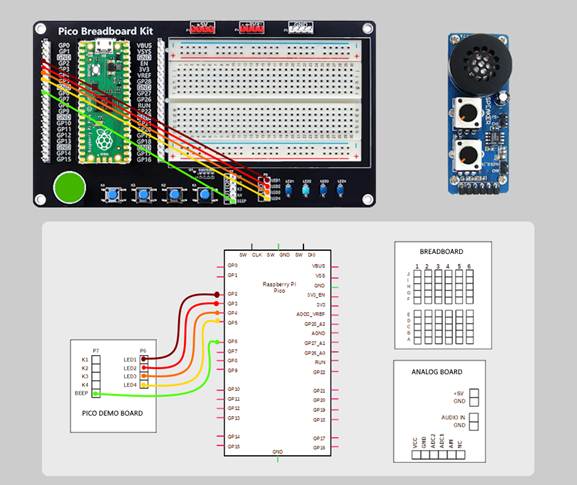
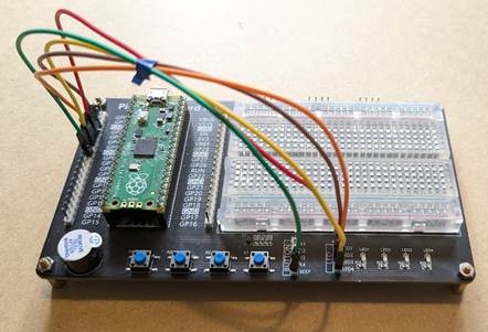
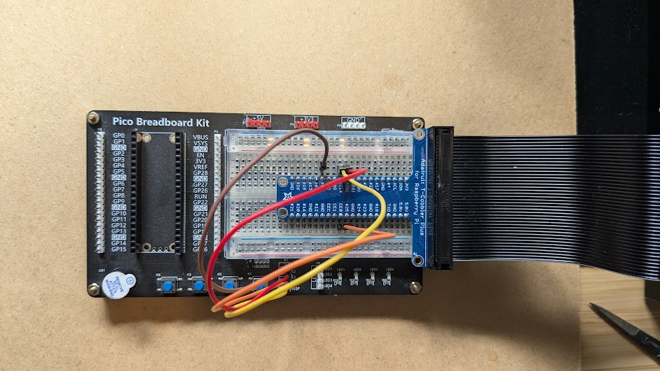
Setting up the Raxda Hardware
Wire your Radxa Hardware to match the images below
Lesson 1 Instructions
The LabVIEW version of a “Hello World” program makes a piece of hardware do something basic, usually turning an LED on and off. In this case, you will also query the device so that it returns its “name.”
A block of code in LabVIEW is called a Virtual Instrument (VI). As such, a LabVIEW program has a *.vi extension and is comprised of two parts. The code resides in the Block Diagram and connects to the Front Panel (or User Interface.) The Front Panel displays data in indicators and receives data through inputs. (see the quick video in this post) An application is comprised of many, if not hundreds or thousands of VIs.
-
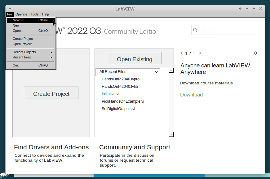
Start LabVIEW
-
Select a New VI.
-
For these lessons, you will want to see the Front Panel and the Block Diagram simultaneously. Arrange the components of the VI, the Block Diagram, and the Front Panel like this:
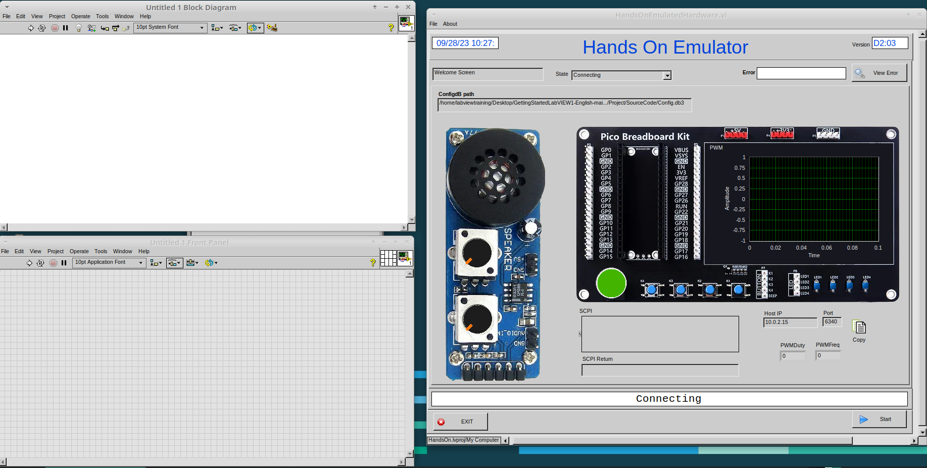
-
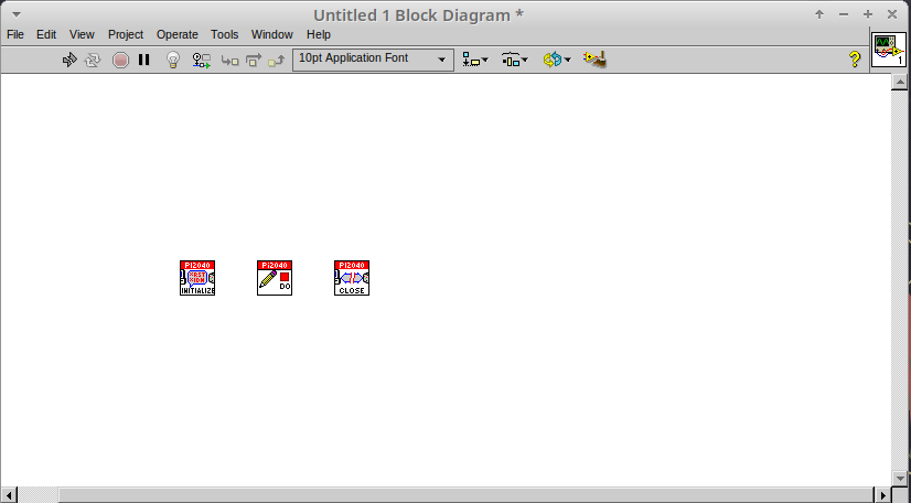
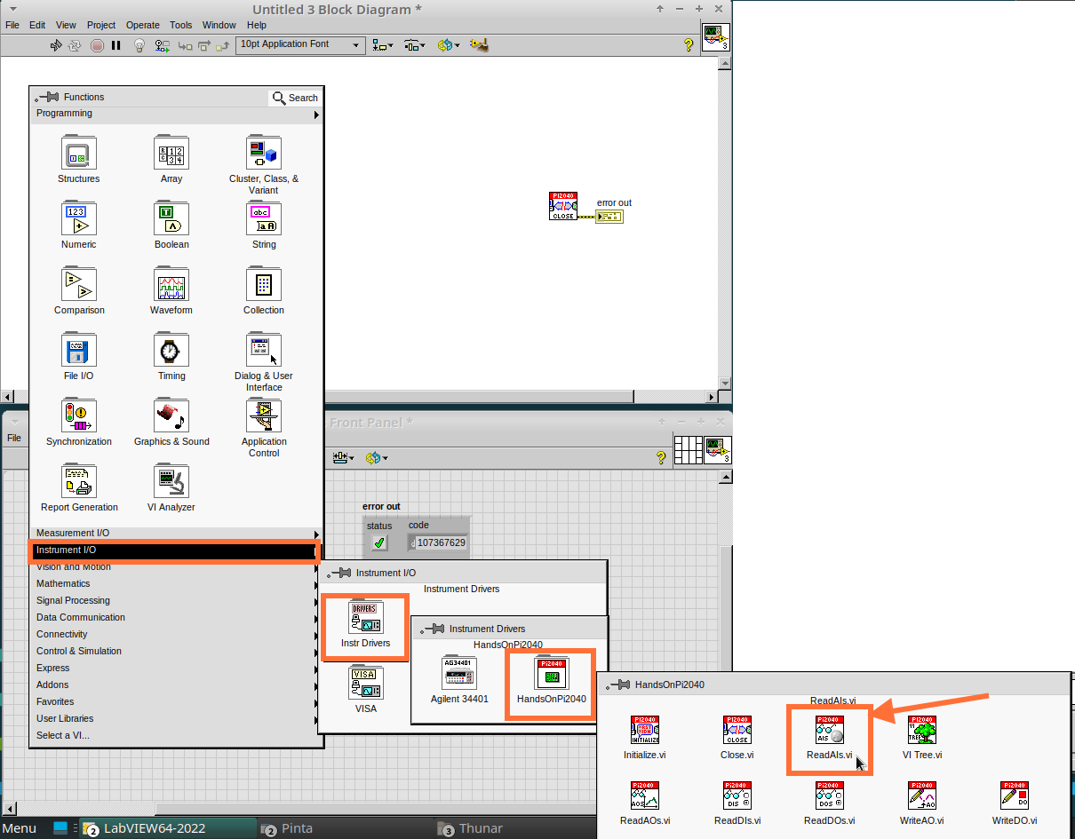
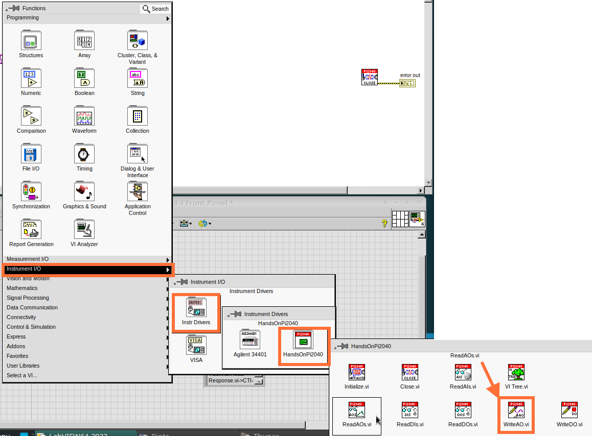
Position the mouse over the Block Diagram and right-click. The Functions Palette opens.
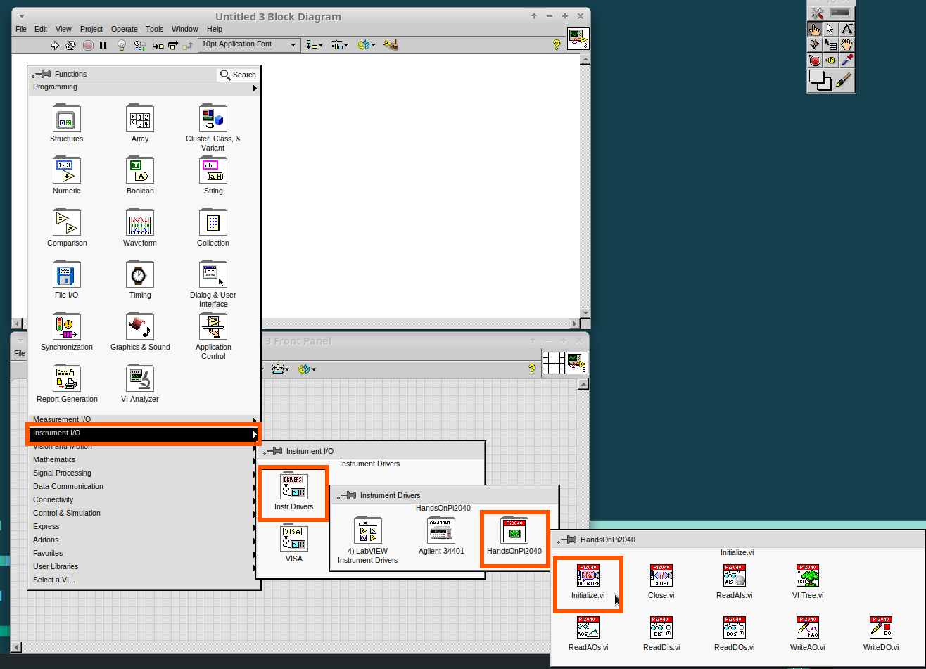
-
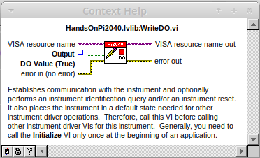
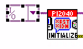
Select and drop the following onto the Block Diagram: Initialize.vi, WriteDO.vi, and Close.vi.
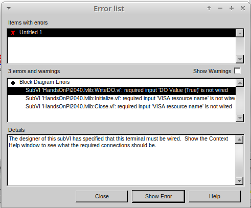
| The Run-arrow is broken (the run arrow appears in the top left corner), if you press it, it will list all the reasons why it`s broken. |
-
LabVIEW will not let you run the source-code until these errors are sorted. Close the Error List and select all of the Vis. (Left-click drag on mouse).
-
Press Ctrl+Space to bring up quick drop and Ctrl+W to wire the VIs together. Quick drop is an extremely useful productivity tool that ships with LabVIEW. It allows you to automate repetitive tasks with a few key combos.
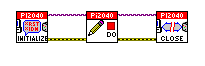
If you press the Run arrow now you will notice that there are only 2 issues listed, good job!
-
Press Ctrl-H to bring up the context help window. Hover over Initialize.vi.
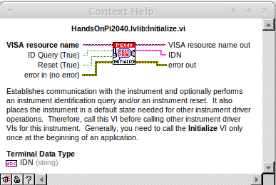
| The VISA resource name is bold. This means that it needs to have an input. |
-
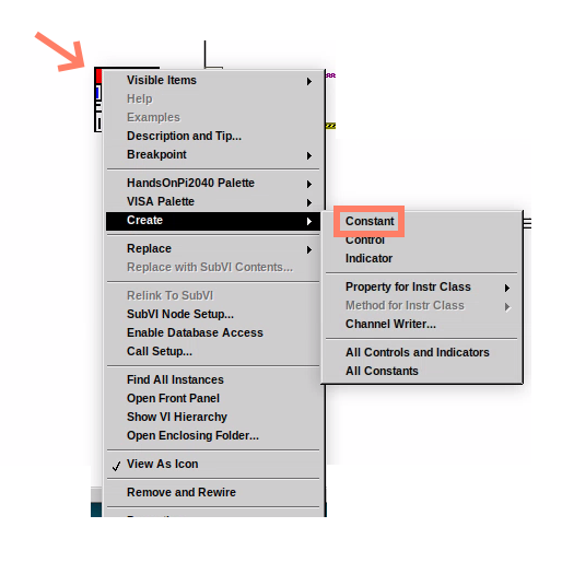
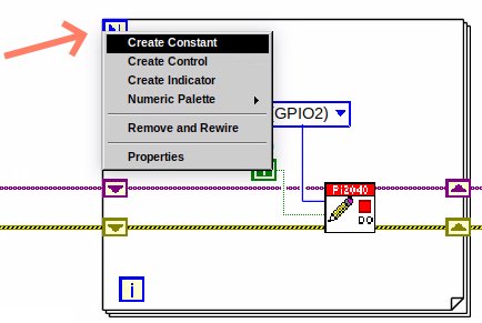
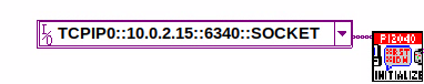
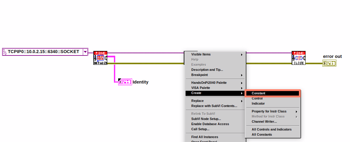
Now, right-click on VISA Resource Name Initialize.vi and select create constant.
If you press the Run arrow now you will notice that there is only 1 issue left.
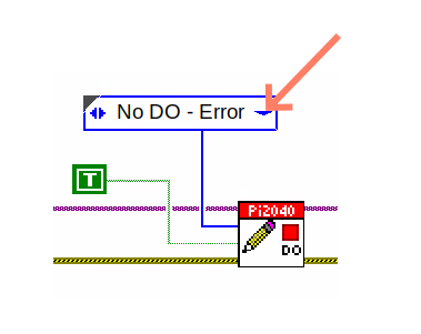
This VI needs its Output and DO Value (True) wiring. So let’s create constants for them. Use the arrow on the right to select an output.
.png)
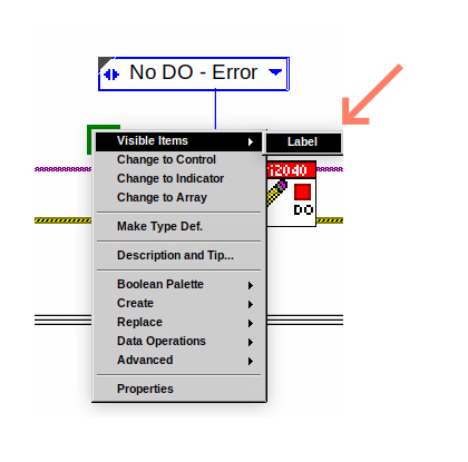
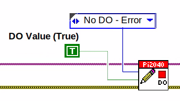
It’s nice to have the constant label shown for booleans.
-
Right-click on the
TrueBoolean Constant. This will bring up a drop down window, hover overVisible Itemsand selectLabel.
We will also need to create a Constant for the VISA Reference Terminal. Like before, Right-click the VISA Resource Name tip strip and create a Constant
Constants are terminals on the block diagram that supply fixed data values to the diagram. We`ll discuss data types etc. later in the session.
-
Finally let’s wire in a couple of outputs.
-
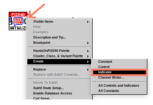
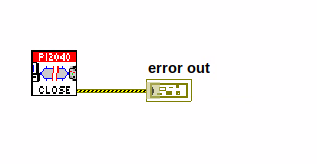
Right-click on IDN for Initialize.vi and select
Create Indicator. Then we need an error out, so Right-click at the bottom the Close.vi and selectCreate Indicator.
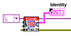
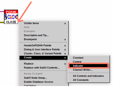
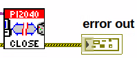
Notice how the Indicators appear on the Front Panel. We`ll discuss block-diagrams and front panels in a bit.
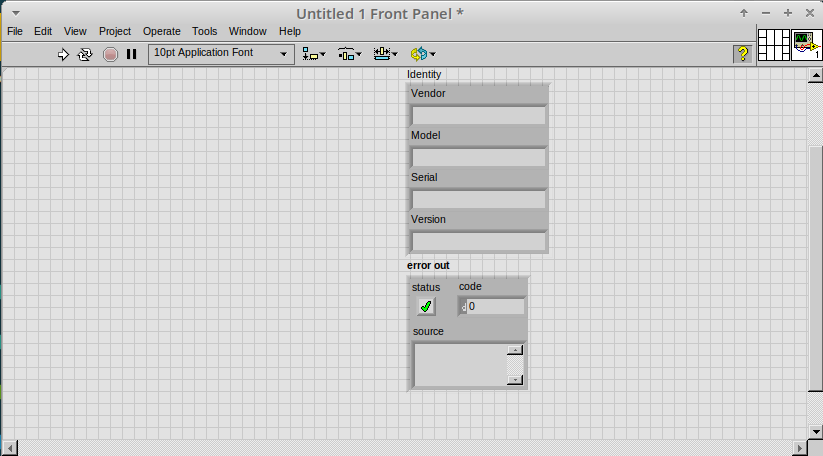
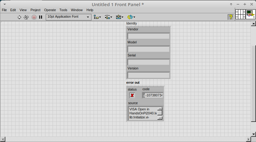
Now we have a running program!
However, you will notice the we`ll have an error.
-
We can interrogate the error message to try and get a clue as to why it all went so wrong. Sometimes it can even be helpful.
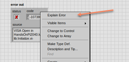
In this case it is!
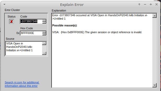
-
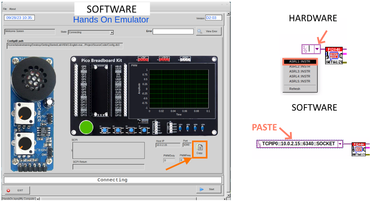
The VIs don`t know who they are talking to. To fix this, hardware users need to set the correct VISA reference from the
VISAdrop down box.. For Emulator users click theCopybutton, as seen in the image below and paste the reference in, if you have hardware refresh and select the ASRL reference.
-
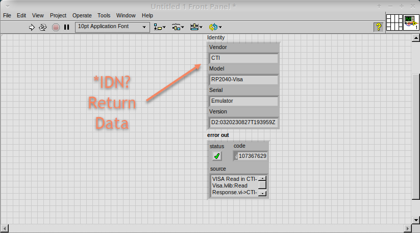
Now press run again.
Here we can see that no errors were apparent and Identity has a value.
But more importantly the LED on the hardware has turned on. image::cm_029.00_LED_Turns_ON.png[]
Lesson 2 – For Loops
| This lesson is optional. |
Optional: Setting up the Hardware
Setting up the Pico Hardware
Wire your Pico Hardware to match the images below
Setting up the Raxda Hardware
Wire your Radxa Hardware to match the images below
Lesson Instructions
A For Loop executes a sub-diagram a set number of times. In this case you will learn how to build a program that will blink the previous LED on and off 10 times each and then stop.
-
Make your workspace bigger to allow space for adding objects. Use Ctrl then drag to expand.
-
Alternatively select the objects you need to move with the selection tool and drag them where you want with the mouse, or using the arrows.
| Press Shift and an arrow key to move selected items quicker. |
-
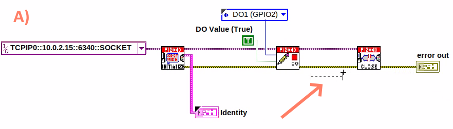
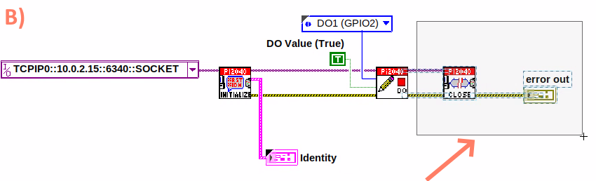
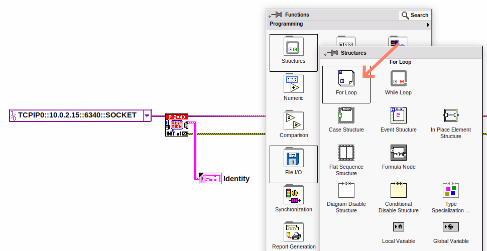
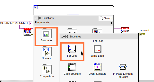
Now insert a For Loop, to do this Right-click anywhere on the block diagram to bring up the functions palette. Select
StructuresthenFor Loop.
-
You will only need to place the For Loop around the WriteDO SubVI (and the constants attached to it.)
-
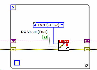
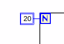
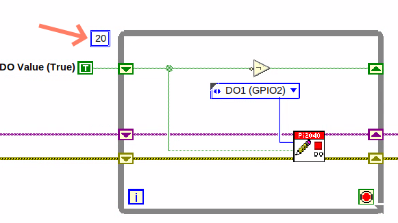
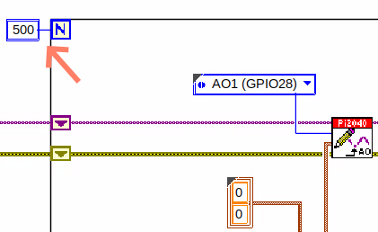
Once the For Loop has been placed, you will see an
Nin the top left corner, this is the loop count (or how many times the loop will execute.) -
Right-click on the left hand side of the Loop Count, and select
Create a Constant. For this task you will need the Loop Count to be 20 (10 times on and 10 times off.)
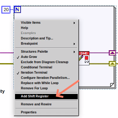
In order for the program to blink successfully it will need to know
what the previous loop has executed, therefore you will need a Shift
Register.
-
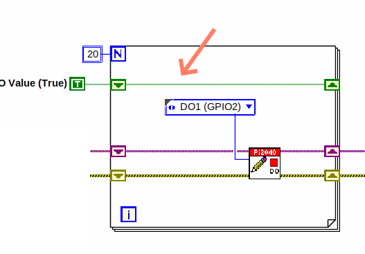
Right-click on the edge of the For Loop and select
Add Shift Register.Wire the True Constant to the Shift Registers and the DO (Value) wire terminal.
-
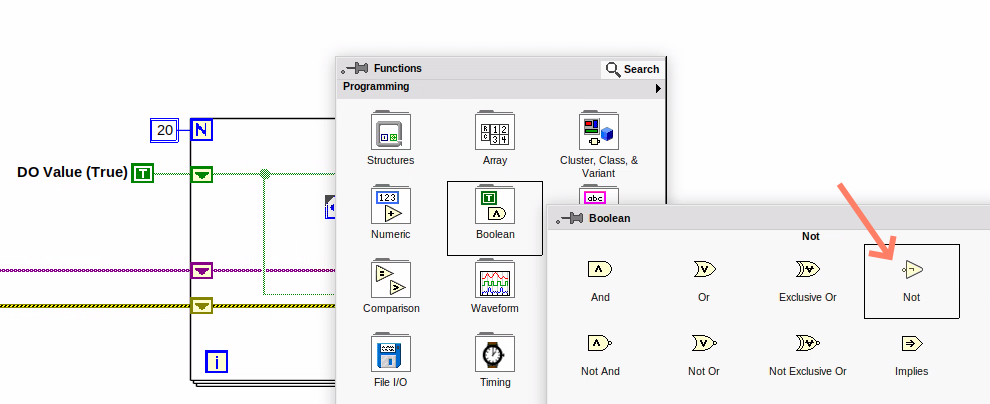
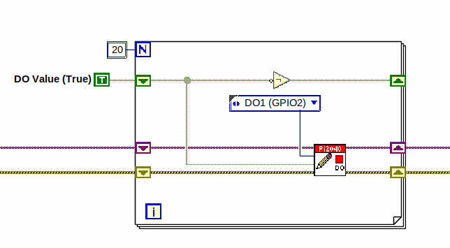
For a blinking LED you will need to invert the boolean value after every loop. To do this Right-click anywhere to bring up the functions palette. Hover over
Booleanthen select theNotBoolean. Wire this into the shift registers. -
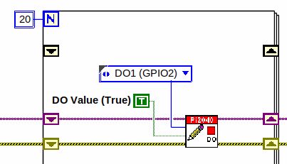
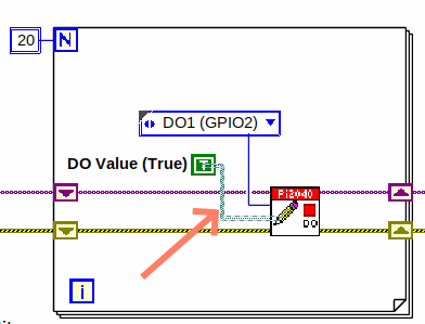
Double click the green wire connecting the True Constant to the SubVI and delete it. Move the True Constant outside the For Loop. Wire the Constant through the For Loop and into the Shift Registers.
-
Remember to wire it back into the SubVI. 040.00_ForLoopWired-TrueFromShiftRegisterToWriteDO.png[]
If you were to run the program at this point the LED would light up, but would not blink.
|
-
For a blinking LED you will need to invert the boolean value after every loop. To do this Right-click anywhere to bring up the functions palette. Hover over
Booleanthen select theNotBoolean. Wire this into the shift registers.
The program will now work! However, it will execute very fast, and you will not be able to see the LED blinking. So you need to slow the Loop down.
-
Right-click inside the For Loop, hover over
Timing.There will see many different timing options. For this you will use theWaitfunction. Select and place inside the Loop. -
Create a constant by Right-clicking on the left side of the
Waitfunction. TheWaitfunction executes in milliseconds, therefore to slow down the Loop by 5 seconds, write 500.
.png)
-
Now Run the program. You have successfully used a For Loop to blink the Digital Output.
Lesson 3 – While Loops
| This lesson is optional. |
Optional: Setting up the Hardware
Setting up the Pico Hardware
Wire your Pico Hardware to match the images below
Setting up the Raxda Hardware
Wire your Radxa Hardware to match the images below
Lesson Instructions
The While Loop executes the sub-diagram until a specific condition occurs. It will always execute at least one time.
In this case, you want the LED to continually blink on and off until a
Stop button is pressed. You can create this using the previously built
program with the For Loop.
-
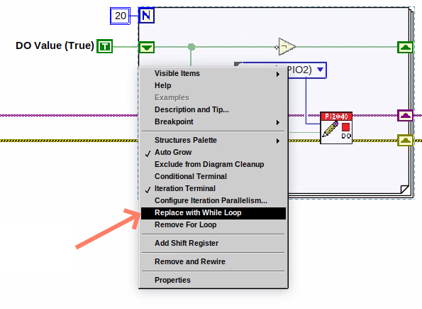
Firstly, Right-click on the edge of the For Loop, and select
Replace with While Loop
-
Now the For Loop has been replaced, the Loop Count is not connected. This is not needed for a While Loop and can be deleted.
-
To add a
Stopboolean, switch to the front panel window and right click where you want to place the button. The Controls palette will appear, selectBooleanand pick a button. The example uses aPush Buttonbut any will work.
-
Back on the Block Diagram move the new Control Boolean into the While Loop and wire it up to the Conditional Terminal in the bottom right corner. If the Button on the Front Panel is pressed when the program is running then the Loop will end and the
blinkingLED will stop.
image::cm_047.00_WhileLoopWired-BooleanSwitchWiredToStopTerminal.png
Lesson 4 – Event Structure
Optional: Setting up the Hardware
Setting up the Pico Hardware
Wire your Pico Hardware to match the images below
Setting up the Raxda Hardware
Wire your Radxa Hardware to match the images below
Lesson Instructions
An Event Structure waits until a certain event occurs, then executes the appropriate case to handle that event. In this example, we want to press a buttons and the corresponding light to turn on.
-
First lets delete the while loop and its contents. Click on the While Loop and press the delete key. Do the same for the
Trueconstant. Then remove the broken wires with Ctrl+B.
-
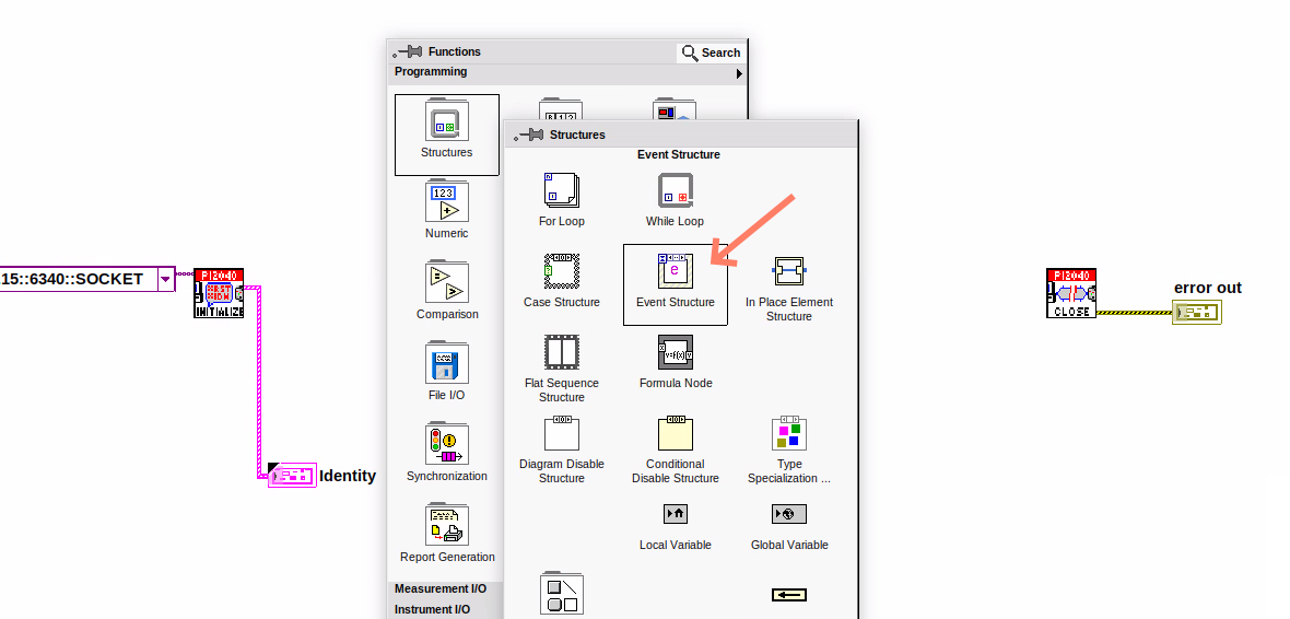
Right-click to bring up the Functions Palette, hover over
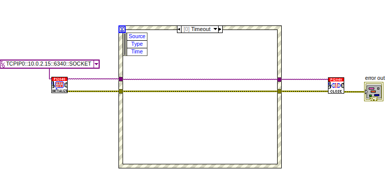
Structuresthen selectEvent Structure.Place the Event Structure on the Block Diagram.
-
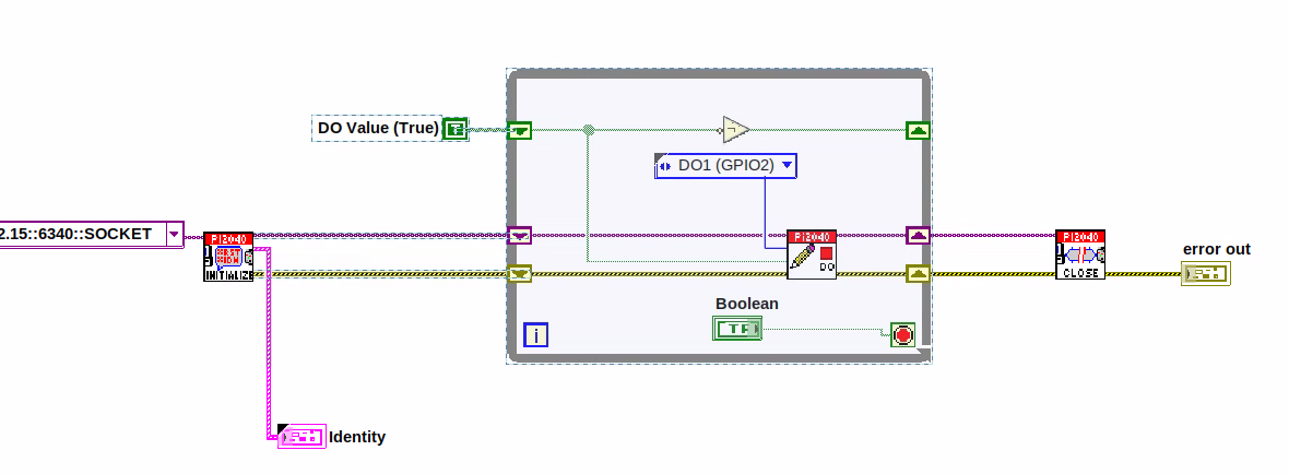
Wire the Initialize VI and the Close VI through the Event Structure.
-
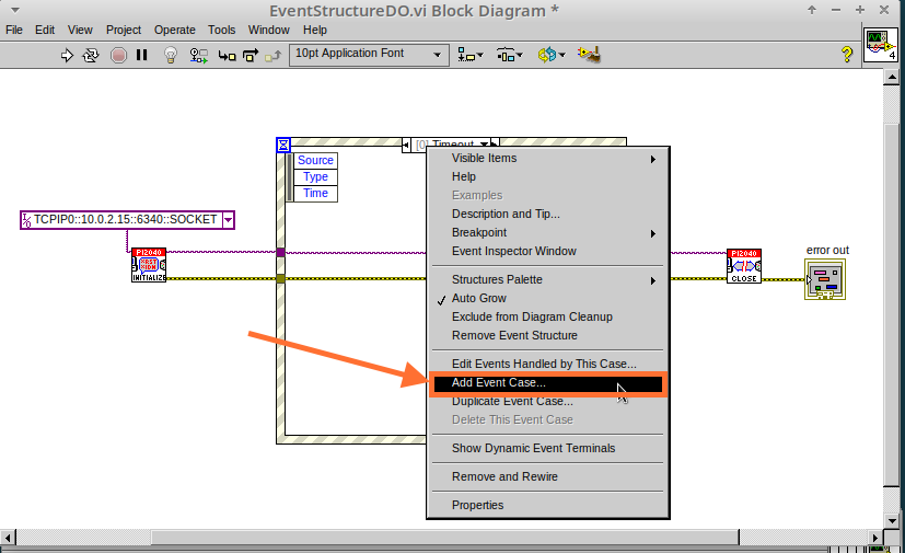
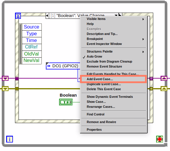
Add a new Event Case by Right-clicking on the Selector Label, and select
Add Event Case.
-
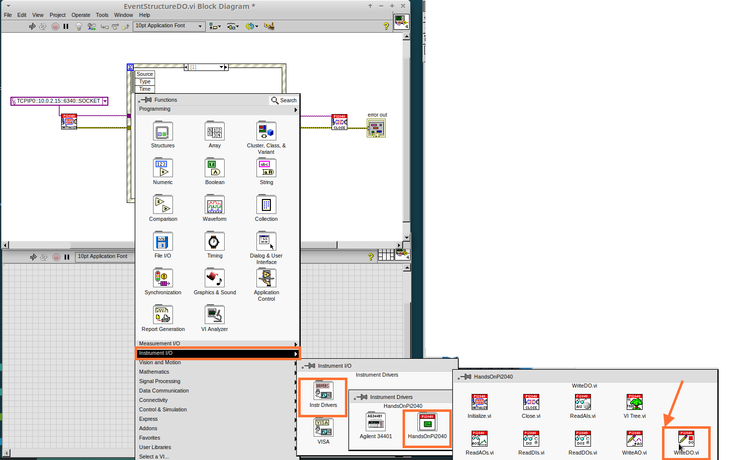
Add the WriteDO.vi by bringing up the Functions Palette, hover over
Instrument I/O,Instr Drivers,HandsOnPi2040,and select `WriteDO.vi.
-
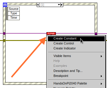
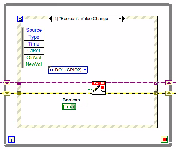
Drag the sub VI inside the Event Structure and wire it up. Right-click the Output terminal and create a Constant.
-
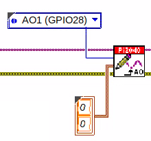
Change the Output from
No DO – ErrortoDO1by clicking the drop down arrow on the Output Constant.
.png)
-
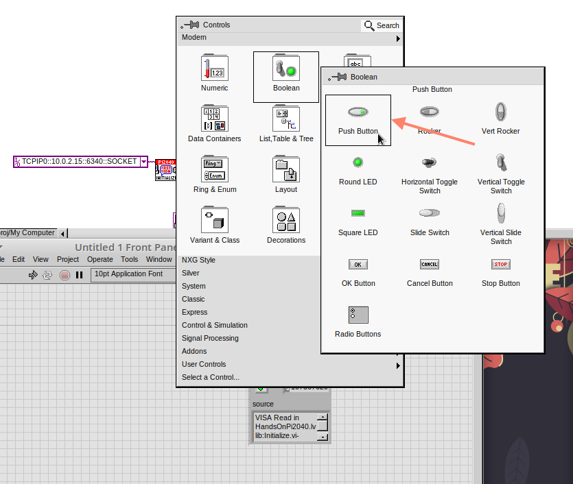
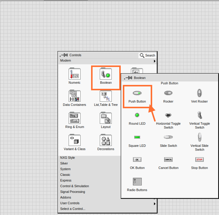
Next we need to add a button for the Digital Output. Go to the Front Panel, and Right-click anywhere to bring up the Controls Palette. Hover over
Boolean,and selectPush Button
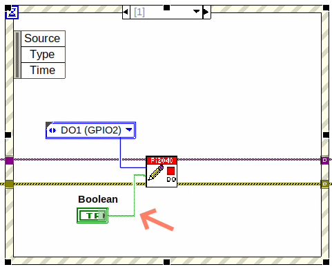
-
Wire the new Boolean Control into the
DO Valueterminal.
-
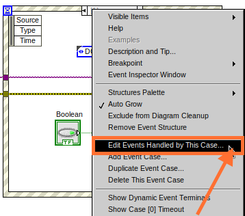
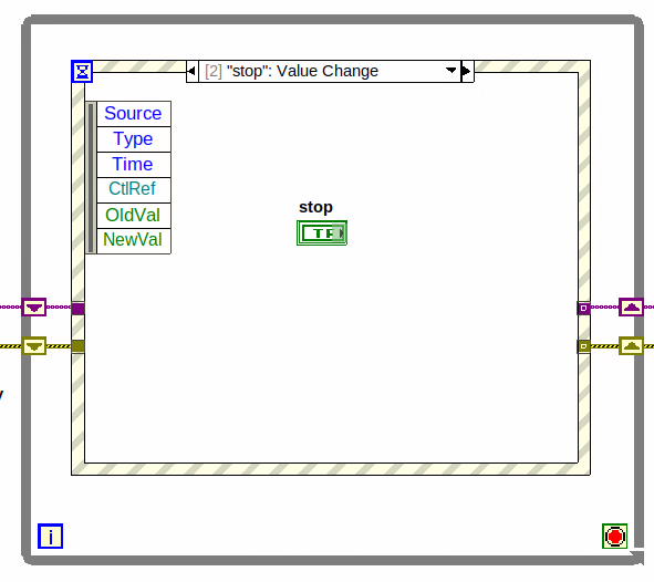
Right-click on the Label Selector as we need to
Edit Events Handled by This Case.
-
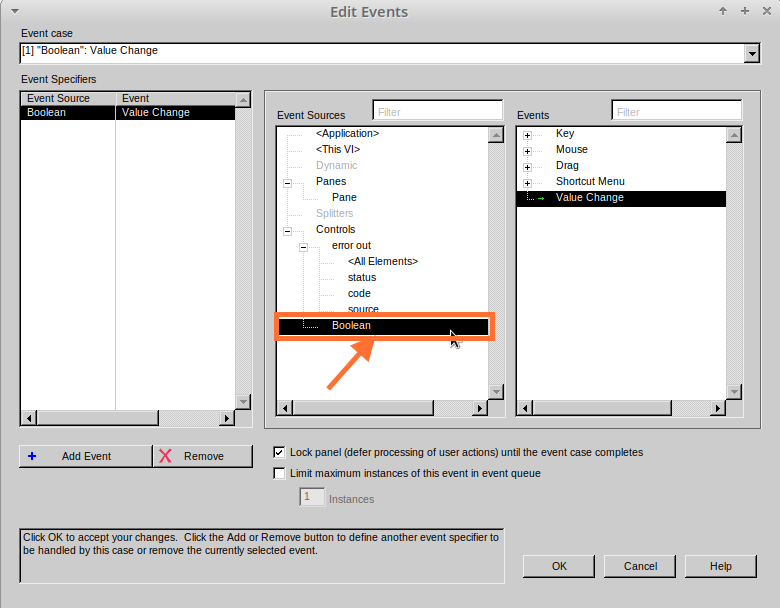
This will bring up the
Edit Eventswindow. SelectBoolean.
-
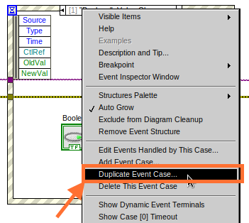
This Event Case is now complete. We will need 3 more Event Cases, each one corresponding to a LED. The easiest way to do this is to Right-click the Label Selector, and select
Duplicate Event Case.
-
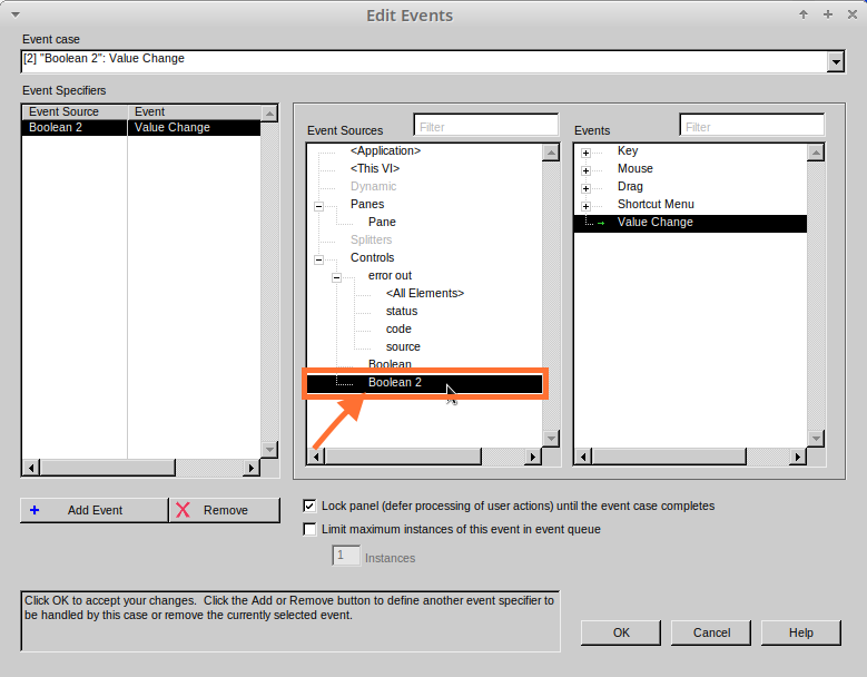
Select
Boolean 2on the Edit Events window.
-
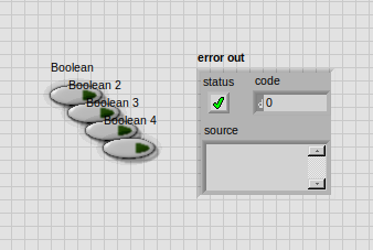
It’s important to change the DO Constant when the case has been duplicated. (DO1 for Boolean, DO2 for Boolean 2, etc.) Duplicate this case 2 more times for DO3, and DO4.
.png)
-
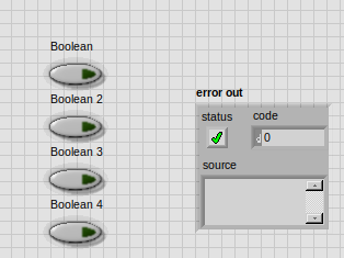
At this point your Front Panel may look a little messy, take some time to clean it up. This will make it easier to use when you have finished building the program.
| You will be able to Run the program now, however, it will Stop after one Boolean has been selected. We can make this more efficient. |
-
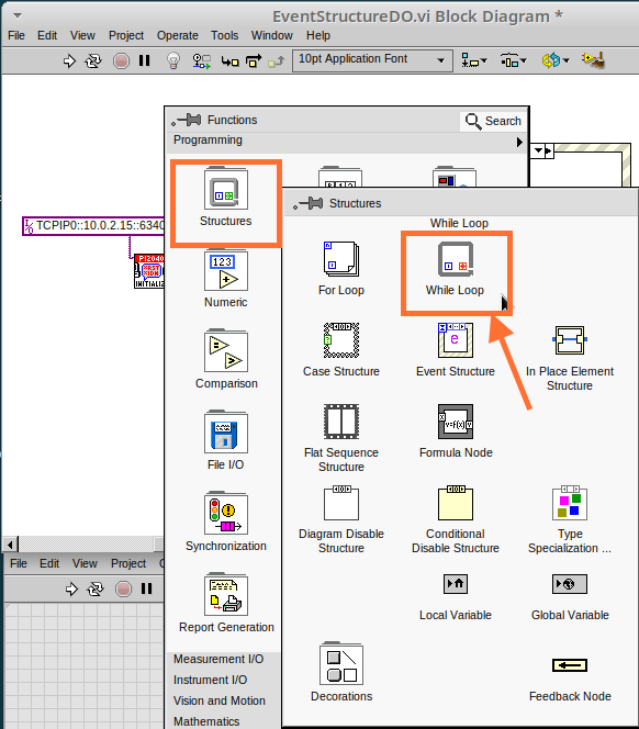
Back on the Block Diagram we will need to add a While Loop. Right click to bring up the Functions Palette, hover over
Structuresand selectWhile Loop.
-
Place the While Loop around the Event Structure.
-
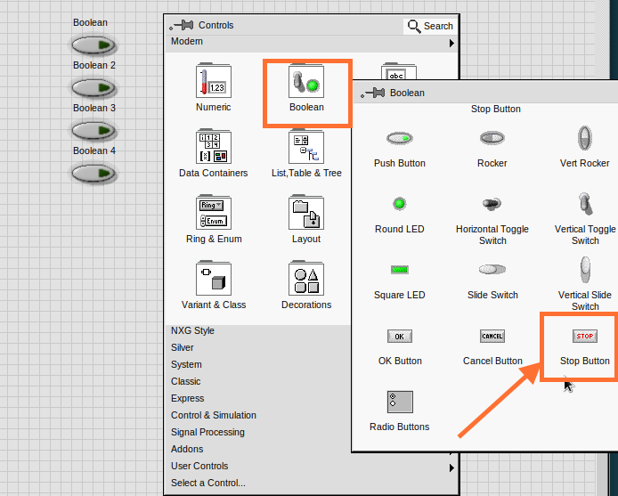
Go to the Front Panel, so we can add a
Stopbutton that we`ll connect to the Loop Condition. Right-click to bring up the Controls Palette, hover overBoolean, then select `Stop Button.
-
We will also need to create a new Event Case for this Stop button. Right click on the Selector Label and select
Add Event Case.
-
Place the
Stopcontrol inside the new case.
-
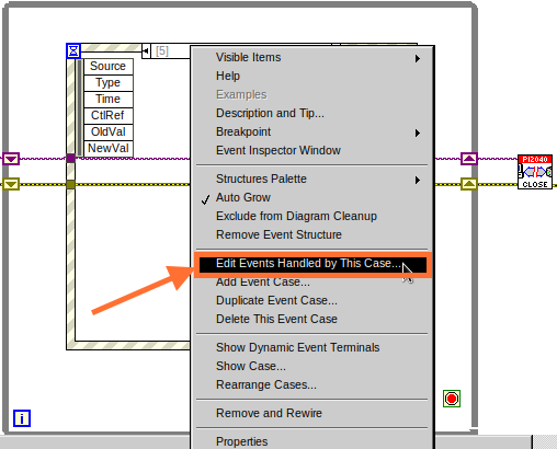
Right-click the Selector Label and select
Edit Events Handled by This Case
-
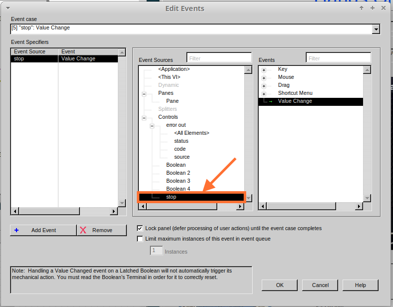
When the
Edit Eventswindow pops up choose thestopoption in theEvent Sourcestable.
-
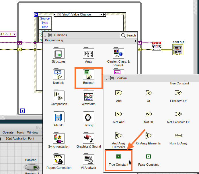
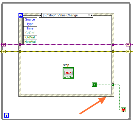
Our last step is to wire a
Trueconstant to the Loop condition. Right click to bring up the Functions Palette, hover overBooleanand selectTrue Constant. -
Place the Constant inside the Event Structure.
-
Wire the constant to the Loop Condition, like the image below.
-
The program will now run successfully. You will be able to turn the LEDs on and off as many times as you want. You can use the Stop button to stop the execution of the program.
==
Lesson 5 – Numbers, Graphs and Charts
Optional: Setting up the Hardware
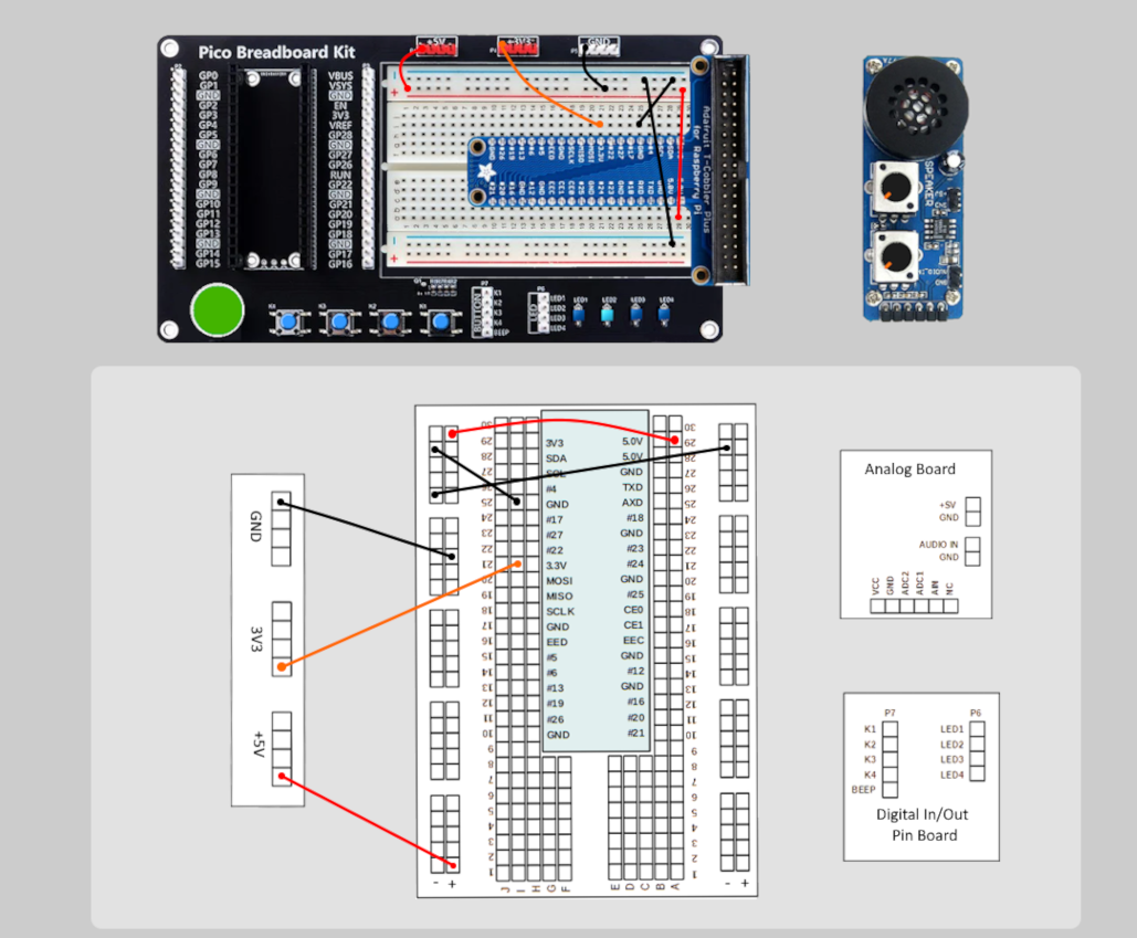
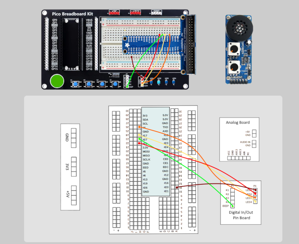
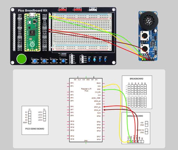
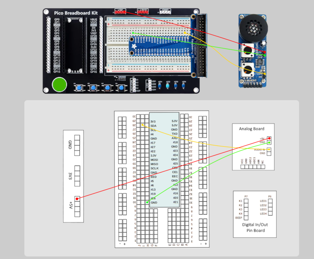
Setting up the Pico Hardware (Analog Input)
Wire your Pico Hardware to match the images below
Setting up the Raxda Hardware (Analog Input)
Wire your Radxa Hardware to match the images below
Lesson Instructions
Analog Input
Now you have made working programs using Digital Inputs and Outputs, it`s time to have a look at the Analog Inputs and Outputs.
For this lesson you will be focusing on the Analog Inputs.
-
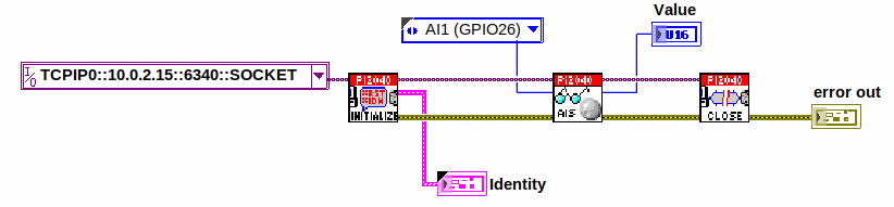
Like the lessons before, start with placing the Initialize.vi, and the Close.vi on a new Block Diagram.
-
Right-click to bring up the Functions Palette. Follow along with the image below and place the ReadAI.vi on the diagram.
-
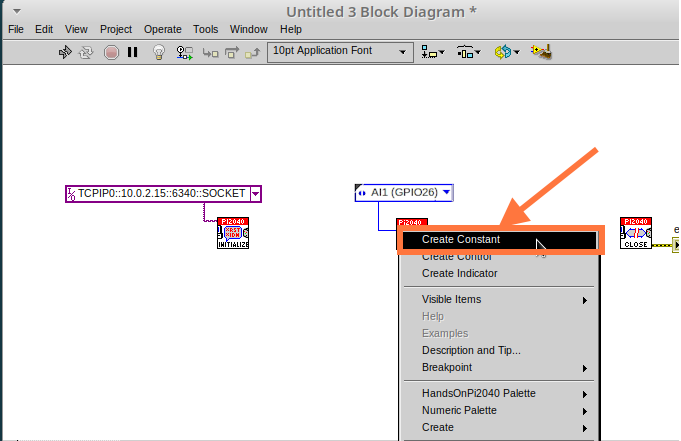
You want to create a constant by Right-clicking on Analog Input on the left of the ReadAIs.vi, and selecting Create Constant.
-
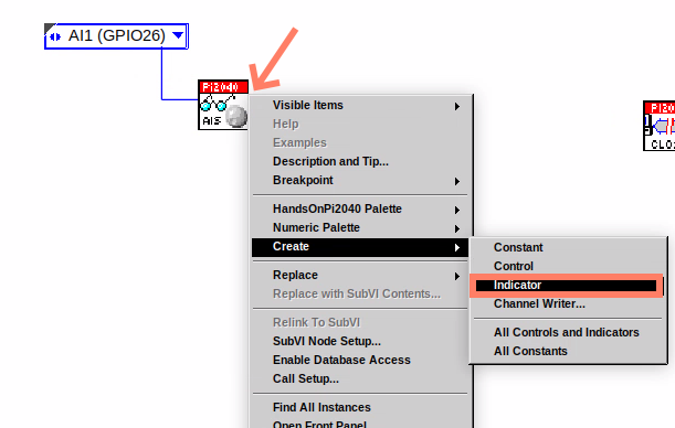
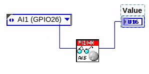
Create an Indicator for the Analog value on the right side of the vi.
-
Wire your program like the image below.
| The program will successfully run at this point, however, it will execute too fast to move the Analog Sticks for continuous data. |
-
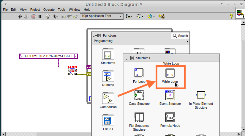
To fix this issue, you can add a While Loop. Bring up the Functions Palette, then
Structures, and selectWhile Loop. Place this around the ReadAIs.vi, but leave space for other functions.
-
A While Loop will not work without adding a Loop Condition. In most cases this will simply be a Stop Boolean. Right-click on the Loop Condition and
Create Control.
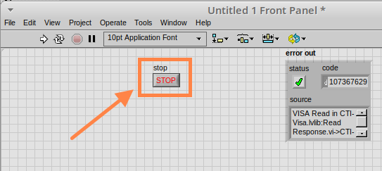
| This will automatically add a Stop Boolean onto the Front Panel. |
-
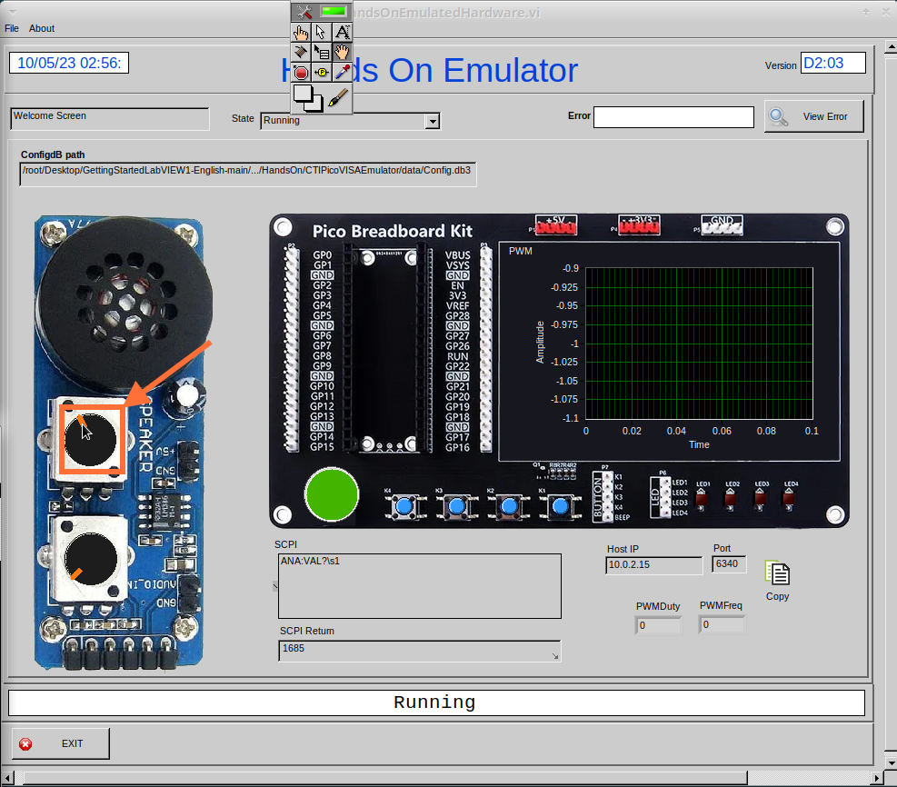
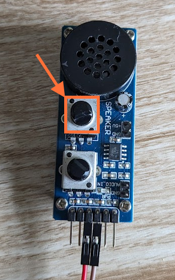
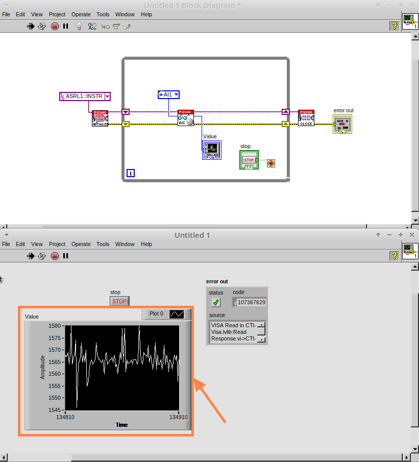
You can run the program now and when you turn the Analog Sticks the value will show.
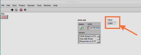
If you are using physical Pico Bread Board and Analog Board you will notice the Value Indicator will flicker between numbers, this is normal and is simply extra noise from the equipment.
|
-
However, it is also possible to replace this with a Chart which will show the data continuously.
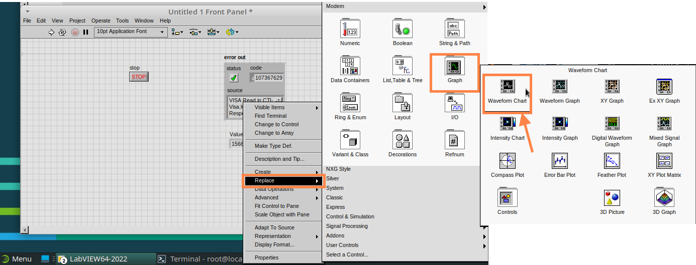
-
Right-click on the Value Indicator, and hover over Replace. This will bring up the Control Palette. Select Graph and then a Waveform Chart.
Optional: Setting up the Hardware
Setting up the Pico Hardware (Analog Output)
Wire your Pico Hardware to match the images below
Setting up the Raxda Hardware (Analog Output)
Wire your Radxa Hardware to match the images below
-
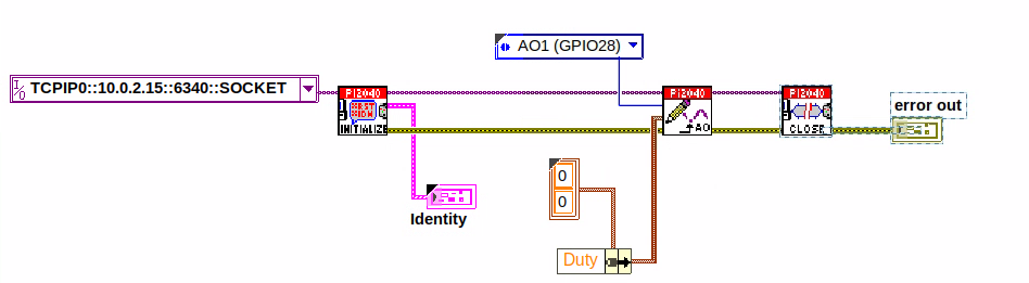
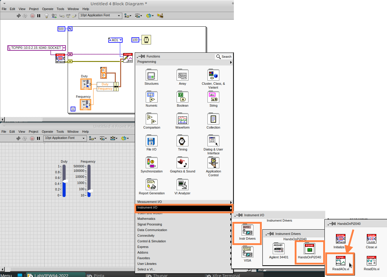
Beginning with a Block Diagram with an Initialize.vi and a Close.vi. Right-click to bring up the Functions Palette. Follow along with the image below and add the WriteAO.vi onto the diagram.
-
Wire up the 3 VIs.
-
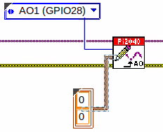
Right-click on the
Analog Outputterminal and Create a Constant.
-
For this exercise the Analog Output will produce 2 different pieces of numerical data, therefore 2 constants will be grouped into a Cluster. So for now also create a Constant for PWM Settings
-
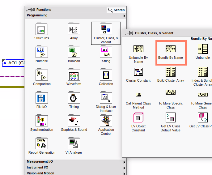
You will need to create a Bundle. Right-click on the Block Diagram to bring up the Functions palette, hover over
Cluster, Class, & Variant, then select `Bundle By Name.
-
Delete the wire connected to the subVI, as it needs to be wired into the bundle you built before.
-
Wire the bundle and the like the image below.
-
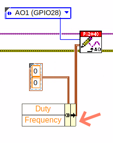
Once wired up, you will notice that the bundle has the label
Duty. Expand the Bundle down so theFrequencylabel is visible.
-
Right-click at the edge of the bundle and create Constants for
DutyandFrequency.
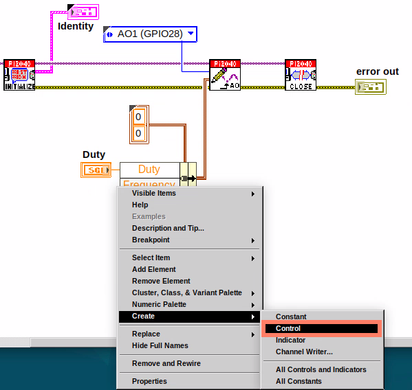
-
The front panel should look like the image below. However, this needs some adjusting.
Using Numeric Control may be a little fiddly when the program runs, so in this case you will swap these out for Vertical Pointer Slides.
|
-
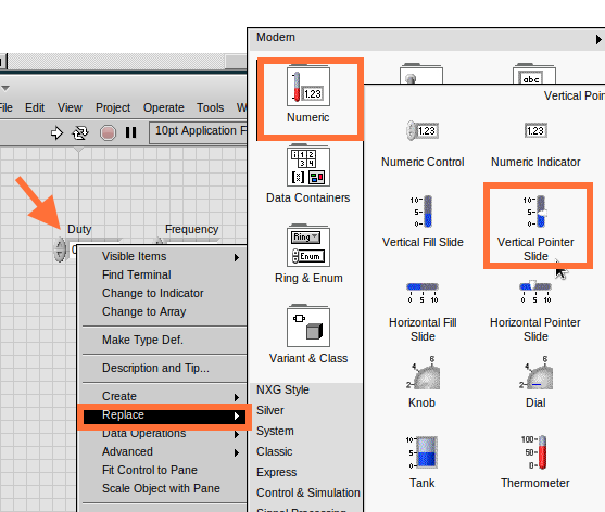
Right-click on the
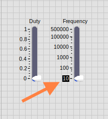
DutyControl and hover overReplace.SelectNumericand thenVertical Pointer Slide.Do the same for theFrequencyControl. -
You will need to change the
Scaleof theFrequencyslider. Right-click on the Slider, selectScale,Mapping, thenLogarithmic.
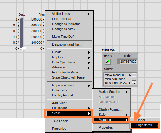
| A logarithmic scale is useful when the data you are displaying is much less or much more than the rest of the data, or when the percentage differences between values are important. |
-
The
Dutyslider can stay as a Linear scale.
-
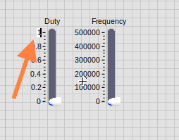
Now you need to set the top and bottom points on the sliders. You will only need to change the highest point for
Duty. Set it to1. -
For
Frequencythe lowest point should be10and the highest500,000.
| Now let’s head back to the Block Diagram and finish building the program. |
-
Bring up the Functions Palette by Right-clicking on the Block Diagram, hover over
Structuresand select a For Loop. Place the For Loop around the WriteAO.vi.
-
A For Loop needs a
Loop Count.Choose a number that will allow you to time to use the dials and see how it executes on the Waveform Chart.
-
You will need to slow down the Program before running it. Bring up the Functions Palette, select
Timingand place theWait (ms)function inside the For Loop.
.png)
-
Right-click the left hand terminal on the Wait function and create a Constant. Type in
100this will slow the program down enough for you to see the results.
Wiired100Constant.png)
-
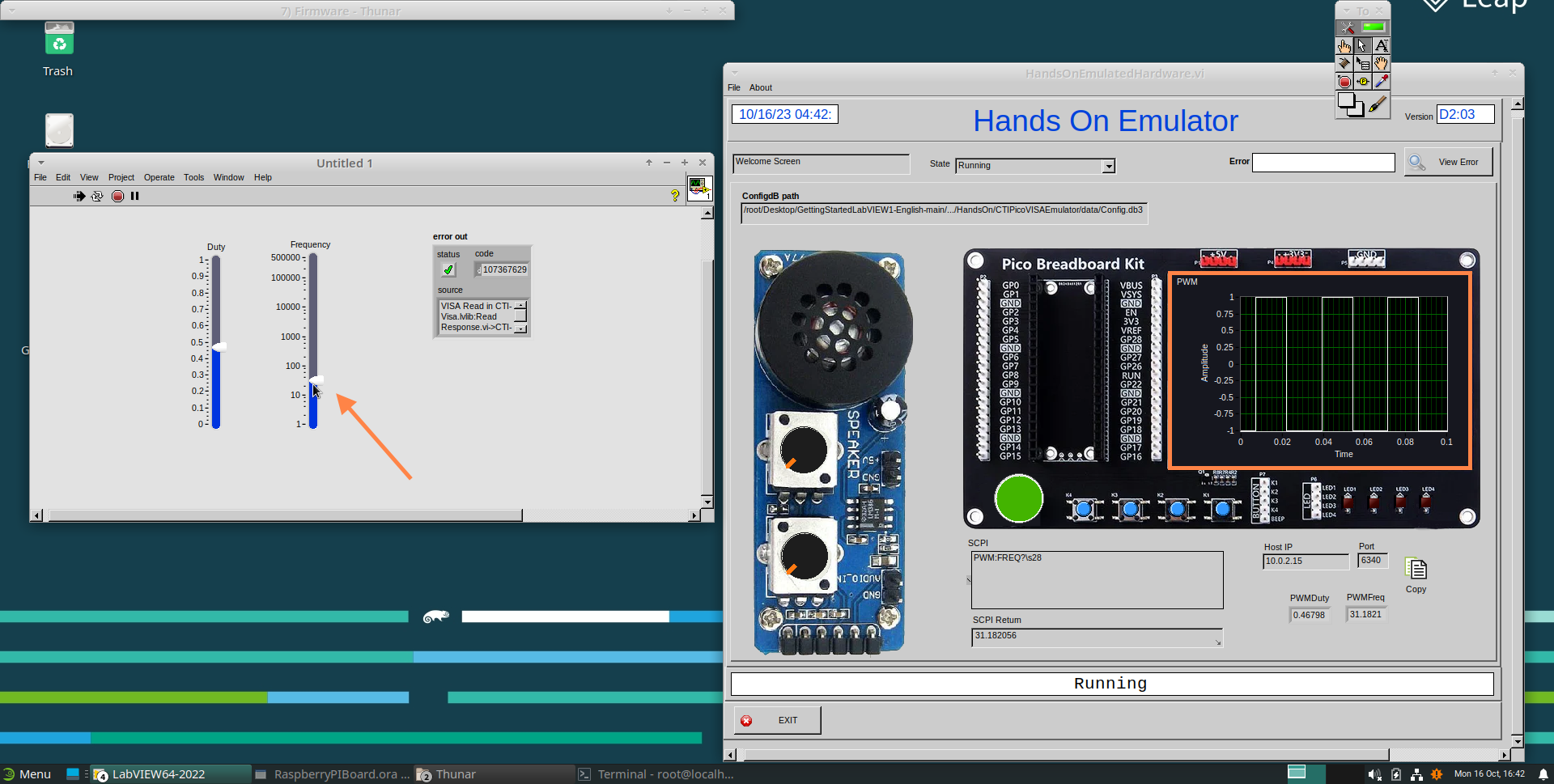
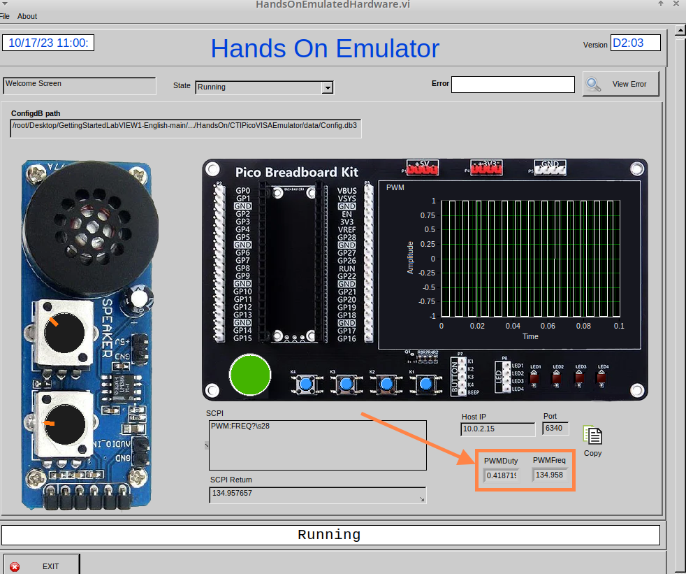
You can now run your program. Move the Vertical Pointer Slides up and down and you will be results will show on the Emulator.
Analog Output (Read)
If you want a more accurate representation for the Duty and
Frequency sliders you can use the ReadAOs.vi.
Place the ReadAOs.vi inside the For Loop by repeat the same process you learnt at the beginning of the Analog Output (Write) lesson.
-
Wire the subVI as show in the image below. Right-click on the
AnalogOutputterminal and create a Constant, then create an Indicator for theAnOutValues.
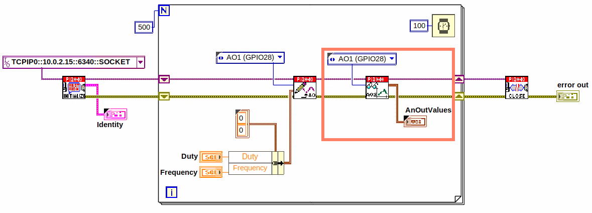
-
You can now run the program, and you will see the Values for
DutyandFrequencyon the Front Panel.
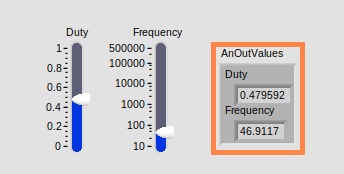
| If you are using the Simulator the values for both will appear on the Emulator. |
General Concepts
VIs (Virtual Instruments)
Programs in LabVIEW are called VIs (Virtual Instruments). In other programming languages a VI is similar to a function or a subroutine. A VI includes a Front Panel and a Block Diagram, the VIs Icon and its Connector Pane.
- Front Panel
-
The front panel window is the user interface for the VI. You create the window with controls and indicators, these are the interactive input and output terminals of the VI.
- Block Diagram
-
The Block Diagram is where you will create the code for your program. The block diagram will implement graphical representations of functions to control the objects on the front panel. Objects on the front panel will appear as terminals on the block diagram.
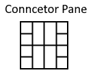
- Icons, Connector Panes, and SubVIs
-
The icon and connector pane allow you to use and view the VI in another VI. This is called a SubVI, to use a SubVI you must build a connector pane. Customising the Icon is recommended to help with reading and understanding the program. The Icon is displayed in the upper right corner of the VI, it is a graphical representation of the VI. The icon can be customised with text and images to help identify what the VI does. The connector pane is a set of terminals on the icon the corresponds to the controls and indicators of the VI.
Data Types
Each variable in a program must have a data type. The data types determines what type of value the variable will hold.
Numeric –
-
Integer (int) – whole numbers (e.g., -700, 0, 700)
-
Floating point (float) – numbers with fractions (decimals) (e.g., 700.0, 0.7)
Boolean – represents 2 states (e.g., true, or false, 1 or 0)
String – sequence of characters, digits, or symbols – always treated as text (e.g., hello)
Enumerated type – predefined unique values (can be text or numerical) (e.g., rock (0) jazz (1)
Character – a single letter, digit, punctuation mark, symbol, or blank space.
Array – stores multiple elements in a specific order. Note: black means no datatype selected. Drop another datatype into the array to make an array of that datatype.
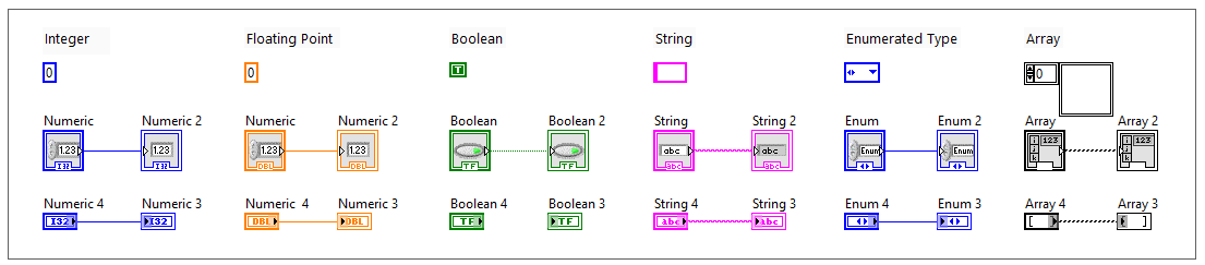
Right-click on a data type terminal and select View as Icon depending on your preference. The 2nd row shows the terminals as icons.
|
While Loops
While Loops allow portions of a program to execute repeatedly until a certain condition is met.
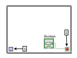
-
Iteration Terminal – the iteration terminal provides the current loop iteration.
-
Conditional Terminal – Evaluates a Boolean input value at the end of each loop iteration, if the conditional terminal is met then the loop stops.
For Loops
A For Loop executes a sub-diagram a certain number of times. This value is wired to the Count Terminal (N).
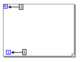
-
Iteration Loop – Indicates the number of completed iterations.
-
Count Terminal – Specifies the number of times to execute the code inside the For Loop.
Event Structures
An Event Structure waits until an event occurs, then executes the appropriate case to handle that event.
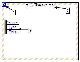
-
The event selector label specifies which events cause the displayed case to execute.
-
The Timeout terminals specifies the number of milliseconds to wait for an event before timing out.
-
The Event Data Node identifies the data LabVIEW returns when an event occurs