Grove Gadgets
Grove has a wide variety of fun toys that can be communicated to using I2C.
Grove Gesture Sensor
Overview
The sensor on Grove - Gesture is PAJ7620U2 that integrates gesture recognition function with general I2C interface into a single chip. It can recognize 9 basic gestures, and these gestures information can be simply accessed via the I2C bus.
Demo Video
This video demonstrates the gesture sensor recognising a gesture and displaying it on the front panel.
Example Code
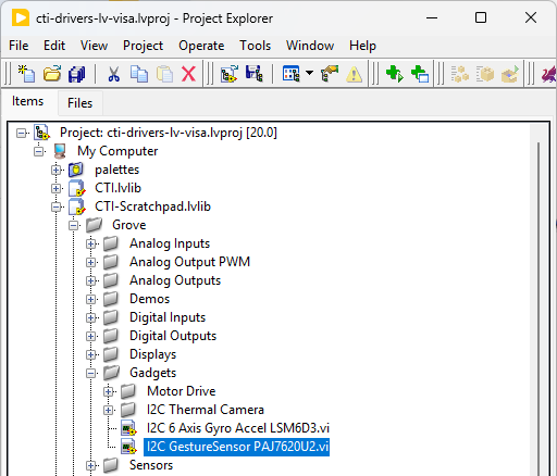
Navigate to >>Scratchpad>>Grove>>Gadgets>>I2C GestureSensor PAJ7620U2.vi
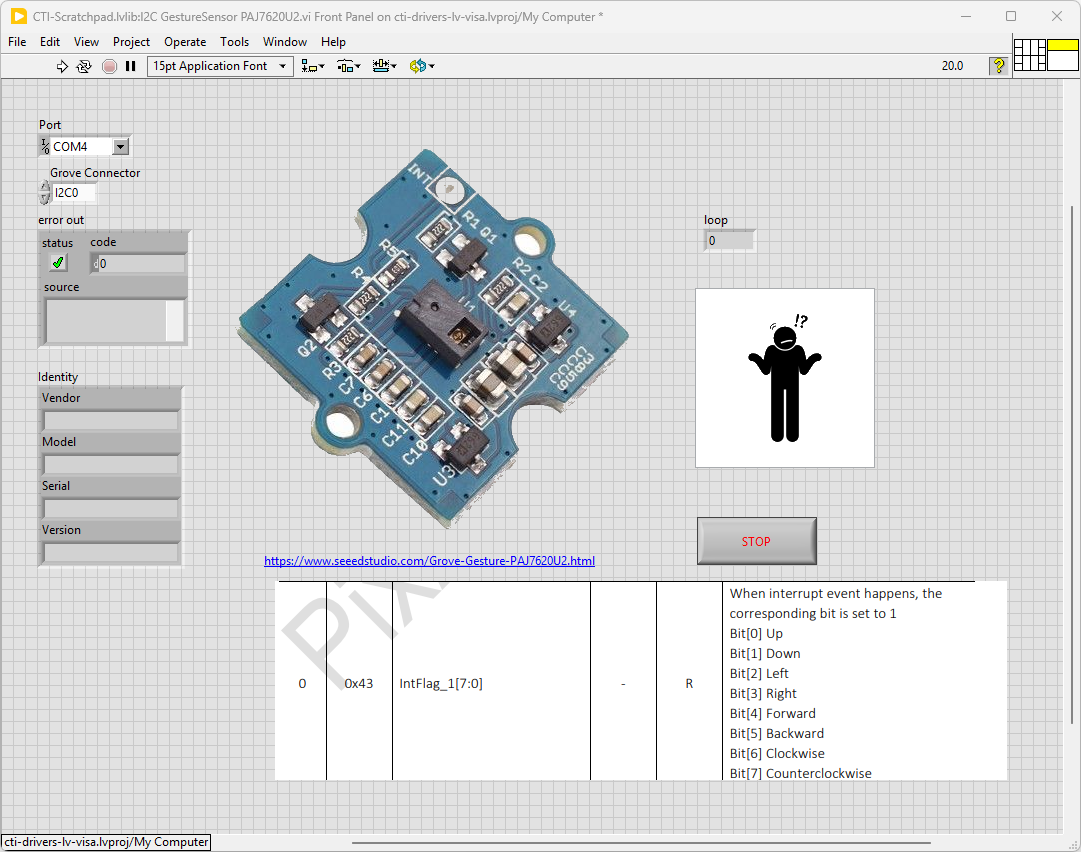
Select the port for the connected Pico and the Grove connector that the board is plugged into. Press the run arrow.
The device will pick up various gestures generated by flapping your hands around in front of it. Works best when the background is not to busy and lit up with light-sources.
On the block diagram you can see that the selected Grove connector dictates the GPIO Pins used for communication. This session connection is input into Grove Gesture Sensor PAJ7620U2.lvclass:Init.
Next we loop round and the while loop and read the detected gesture using Grove Gesture Sensor PAJ7620U2.lvclass:ReadGesture.vi which returns a numbe corresponding with the detected gesture. A picture ring is used to give a nice graphical flourish on the front panel.
Pressing Stop will exit the loop.

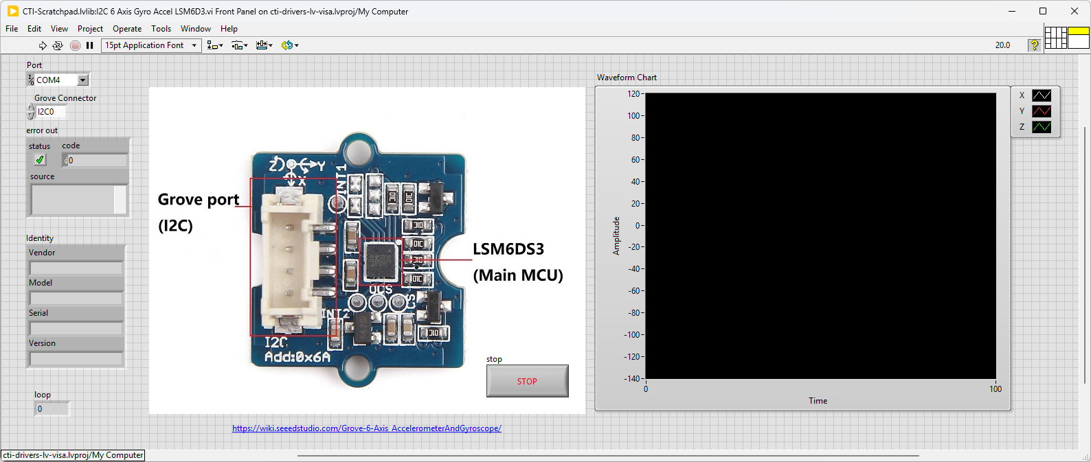
Grove 6 Axis Gyro Accellerometer
Grove - 6-Axis Accelerometer&Gyroscope is a cost-effective Grove interfaced and integrated sensor combination of 3-axis digital accelerometer and 3-axis digital gyroscope.
Demo Video
Shows the Grove - 6-Axis Accelerometer & Gyroscope showing it’s axes being displayed on a graph.
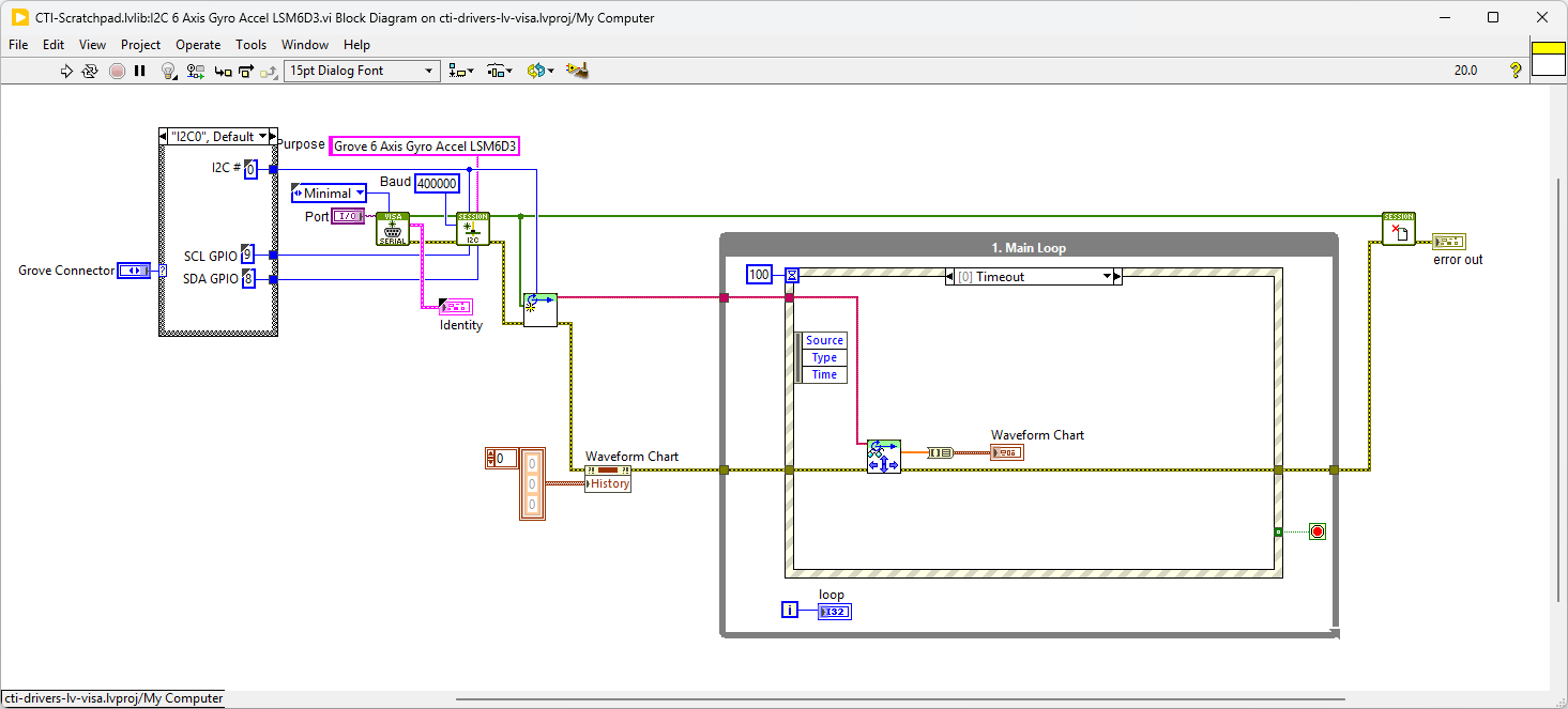
Example Code
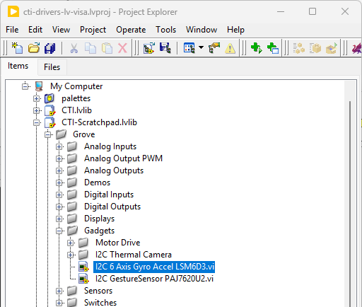
Navigate to >>Scratchpad>>Grove>>Gadgets>>I2C 6 Axis Gyro Accel LSM6D3.vi
This VI polls the 6 Axis controller and displays the X,Y,Z values on a graph. Select the port for the connected Pico and the Grove connector that the board is plugged into. Press the run arrow.
When you move the board you should see a corresponding movement in the graph
On the block diagram you can see that the selected Grove connector dictates the GPIO Pins used for communication. This session connection is input into Grove 6 Axis Gyro Accel LSM6DS3.lvclass:Init. Next we clear the chart and loop round an event structure and use the timeout event to run the Grove 6 Axis Gyro Accel LSM6DS3.lvclass:ReadPosition.vi - this VI returns the latest X,Y and Z values and updates the graph.
Pressing Stop will fire the Stop event and exit the loop.
8x8 Thermal Camera
The Grove - Infrared Temperature Sensor Array (AMG8833) is a high precision infrared array sensor which based on advanced MEMS technology. It can support temperature detection of two-dimensional area: 8 × 8 (64 pixels) and maximum 7 meters detection distance.
Demo Video
Here is a video that shows the set-up and running of the Thermal Camera
This video shows some of the development process
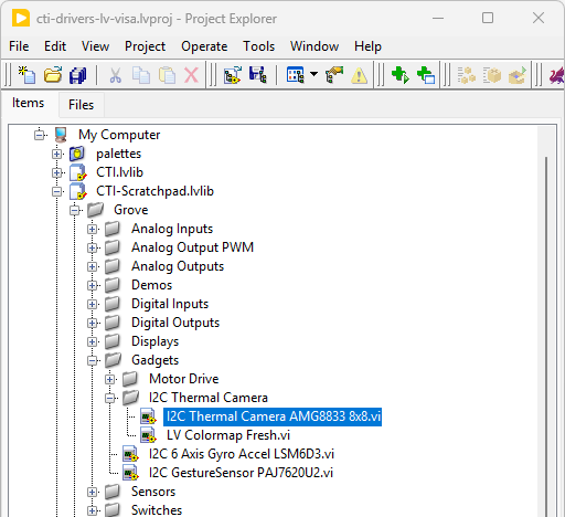
Example Code
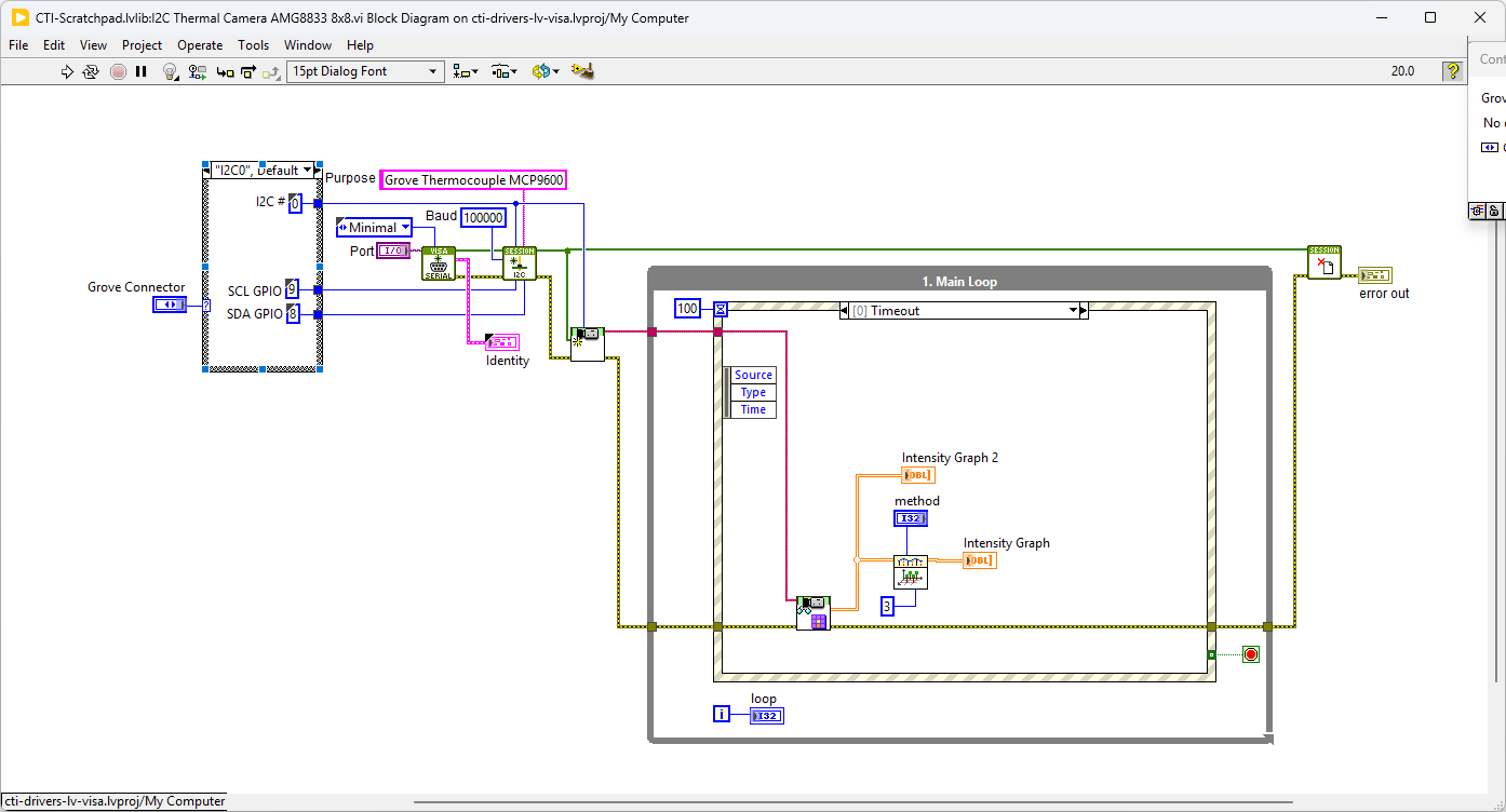
Navigate to >>Scratchpad>>Grove>>Gadgets>>I2C Thermal Camera>>I2C Thermal Camera AMG8833 8x8.vi
This VI uses the AMG8833 to demonstrate interpolation in LabVIEW. Select the port for the connected Pico and the Grove connector that the board is plugged into. Press the run arrow.
The VI will poll the camera and return the 8x8 thermal signal, this will then be interpolated to a higher resolution signal using magic.
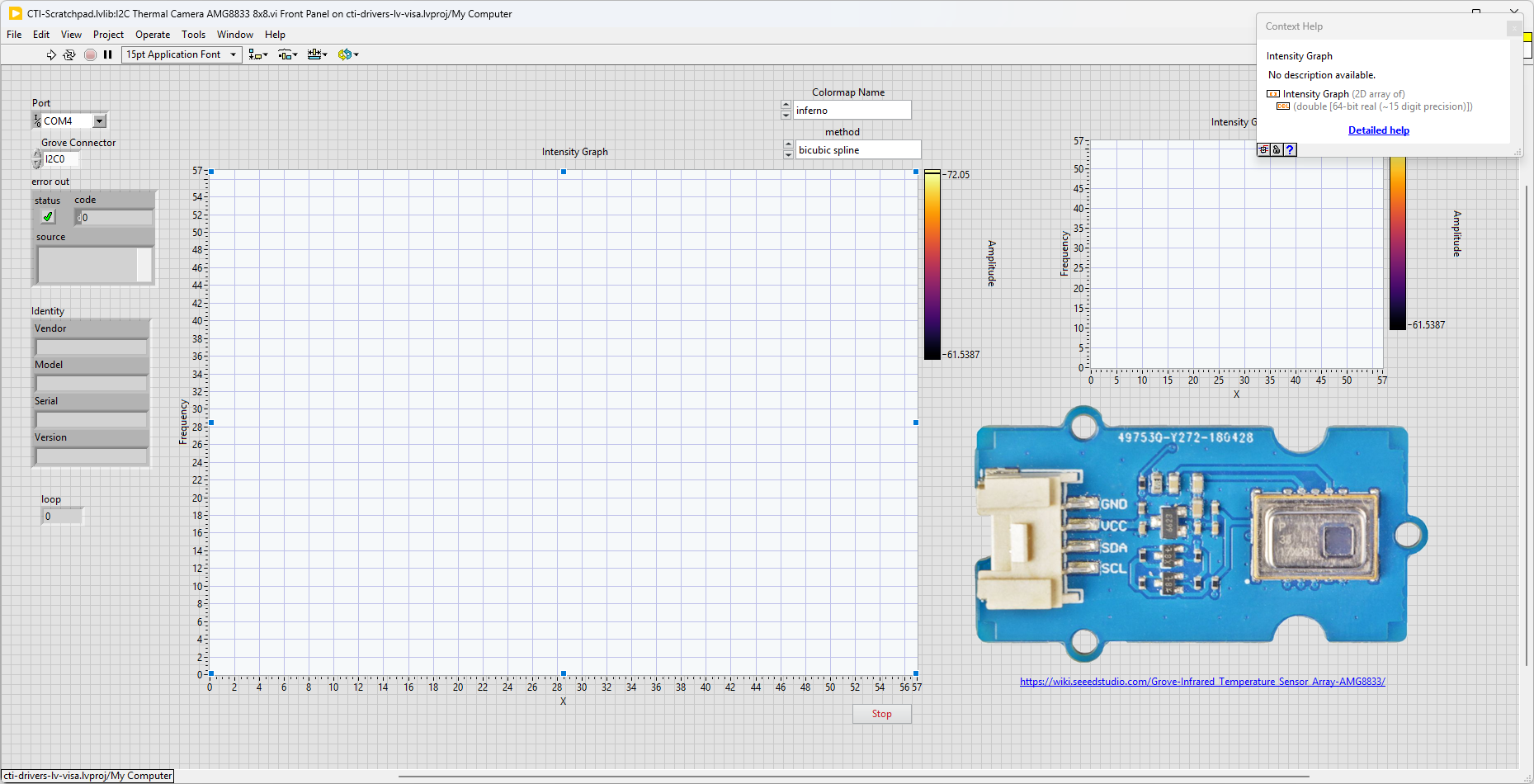
On the block diagram you can see that the selected Grove connector dictates the GPIO Pins used for communication. This session connection is input into AMG8833 8x8 Camera.lvclass:Init. Next we clear the chart and loop round an event structure and use the timeout event to run the AMG8833 8x8 Camera.lvclass:Read Camera.vi - this VI returns and array of values updates the intensity graph. This 8x8 array is put through a 2D Interpolate function that applies the selected interpolation algorithm (bicubic spline seems to work best) and produces a higher reolution signal.
Pressing Stop will fire the Stop event and exit the loop.
L298 Motor Driver
The Grove - I2C Motor Driver V1.3 (latest version) can directly control Stepper Motor or DC Motor. Its heart is a dual channel H-bridge driver chip(L298N)that can handle current up to 2A per channel, controlled by an Atmel ATmega8L which handles the I2C communication with platforms such as Arduino. Both motors can be driven simultaneously while set to a different speed and direction. It can power two brushed DC motors or one 4-wire two-phase stepper motor. It requires a 6V to 15V power supply to power the motor and has an onboard 5V voltage regulator which can power the I2C bus and the Arduino(selectable by jumper). All driver lines are protected by diodes from back-EMF.
Demo Video DC Motor Drive
This video demonstrates the Grove L298 Motor Drive board used with 2 DC motors.
Example Code
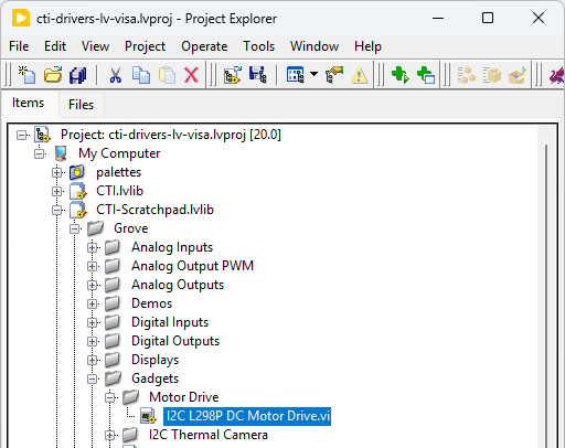
Navigate to >>Scratchpad>>Grove>>Gadgets>>Motor Drive>>I2C L298P DC Motor Drive.vi
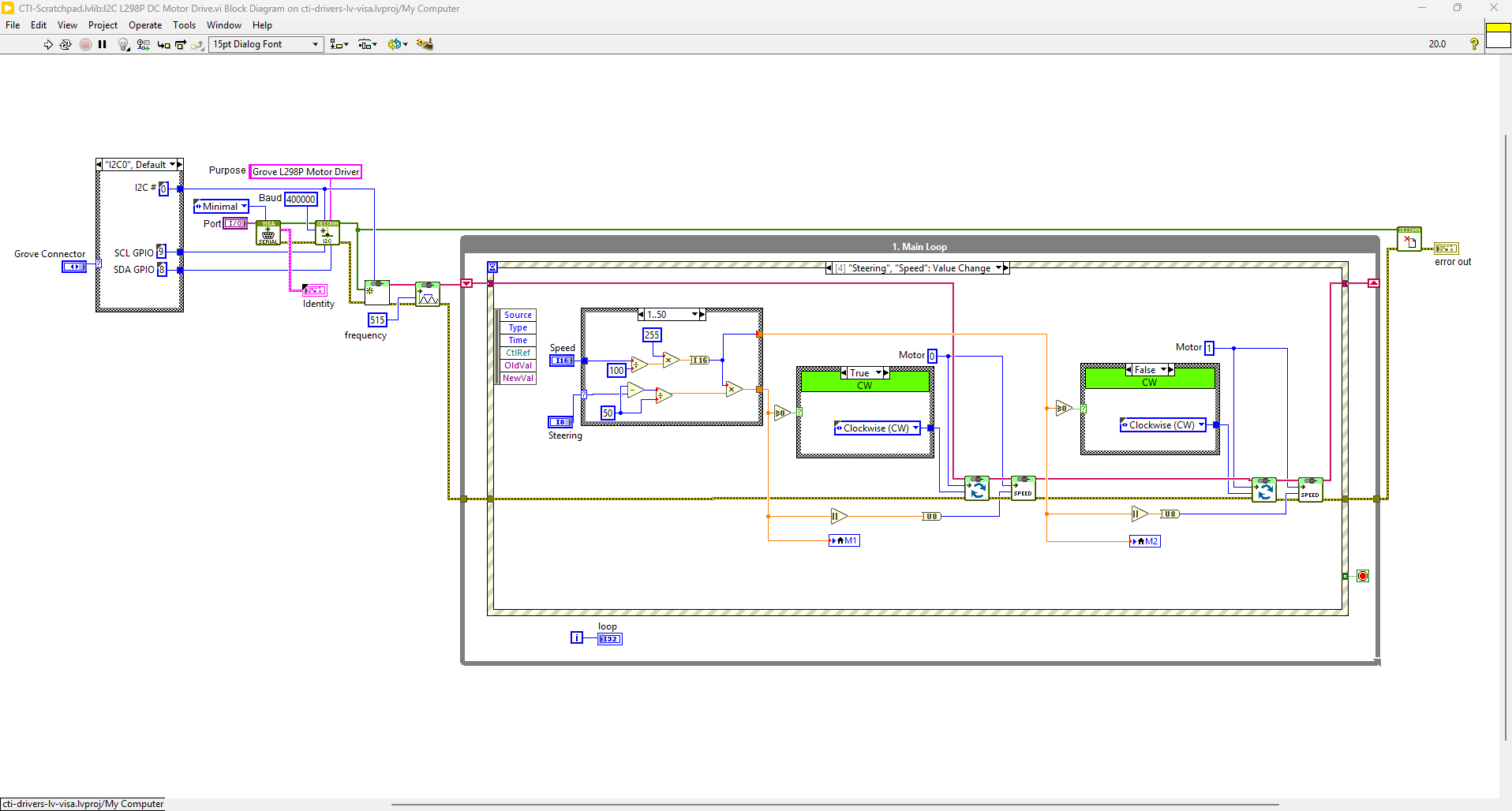
This VI uses the L298P board to rotate 2 wheels forward and backward. Select the port for the connected Pico and the Grove connector that the board is plugged into. Press the run arrow.
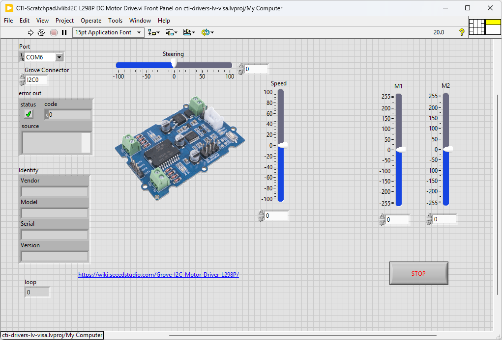
On the block diagram you can see that the selected Grove connector dictates the GPIO Pins used for communication. This session connection is input into Grove I2C L298P Motor Drive.lvclass:Init. Next we set the PWM frequency to 515Hz using Grove I2C L298P Motor Drive.lvclass:Set PWM Frequency.vi. We the loop round the event structure waiting for Value Change events for the Steering, Speed, M1 and M2 sliders. Pressing Stop will fire the Stop event and exit the loop.
Incremental Rotary Encoder
An incremental encoder is a type of rotary encoder that generates a series of electrical pulses as the encoder shaft is rotated. These pulses are used to measure the rotational position, speed, and direction of the shaft.
This particular board is the Adafruit I2C Stemma QT Rotary Encoder with a SeeSaw protocol microcontroller and NeoPixel LED.
Adafruit seesaw is a near-universal converter framework which allows you to add and extend hardware support to any I2C-capable microcontroller or microcomputer. Instead of getting separate I2C GPIO expanders, ADCs, PWM drivers, etc, seesaw can be configured to give a wide range of capabilities.
Hardware Details
This board uses the Qwiic connector, so we will need to use a Qwiic to Grove lead.. These can be bought directly or made to the circuit diagram below.

Example Code
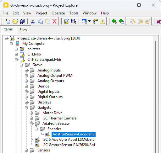
Navigate to >>Scratchpad>>Grove>>Gadgets>>AdaFruit SeeSaw>>Encoder>>AdafruitSeesawEncoder.vi
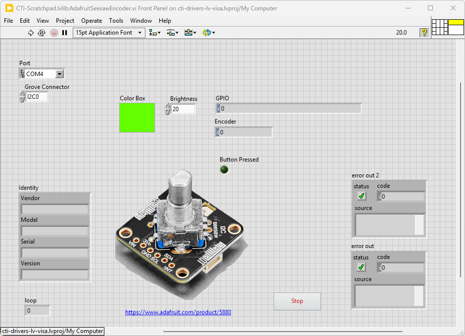
This VI uses the Adafruit Enocder Breakout Board, this board has a small microcontroller running SeeSaw firmware. This gives a lot of functionality through I2C register setting and reading. Select the port for the connected Pico and the Grove connector that the board is plugged into. Press the run arrow.
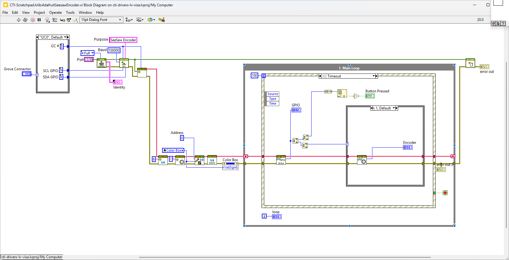
On the block diagram you can see that the selected Grove connector dictates the GPIO Pins used for communication. This session connection is input into AdaFruit-Seesaw.lvclass:Init. Next we set up GPIOs, Encoder and NeoPixel LED using AdaFruit-Seesaw.lvclass:Init:NeoPixelInit.vi,AdaFruit-Seesaw.lvclass:Init:EncoderInit.vi. We then initialise the NeoPixel Buffer by setting AdaFruit-Seesaw.lvclass:Init:SetNeoPixelBuf.vi,AdaFruit-Seesaw.lvclass:Init:NeoPixelShow.vi. We the loop round the event structure in the timeout checking the GPIO pins for the encoder interupt. If the encoder has changed it will read it. Changing the brightness or Color Box will change the Neopixel LED. If you press the rotary encoder a GPIO pin will change, this is caught in the timeout loop. Pressing Stop will fire the Stop event and exit the loop.
Adafruit SeeSaw SAMD09 Micro-Controller
Adafruit seesaw is a near-universal converter framework which allows you to add and extend hardware support to any I2C-capable microcontroller or microcomputer. Instead of getting separate I2C GPIO expanders, ADCs, PWM drivers, etc, seesaw can be configured to give a wide range of capabilities.

As an example the ATSAMD09 breakout with seesaw offers
3 x 12-bit ADC inputs 3 x 8-bit PWM outputs 7 x GPIO with selectable pullup or pulldown 1 x NeoPixel output (up to 170 pixels) 1 x EEPROM with 64 byte of NVM memory (handy for storing small access tokens or MAC addresses) 1 x Interrupt output that can be triggered by any of the accessories 2 x I2C address selection pins 1 x Activity LED