Grove Displays
Grove has a wide variety of displays that can be communicated to using I2C.
HD44870 LCD Display with RGB Backlight Controller
Overview
The LCD display is a useful, robust low power way show system information. The RGB backlight also can convey extra information like Warnings and Alerts.
Example Code
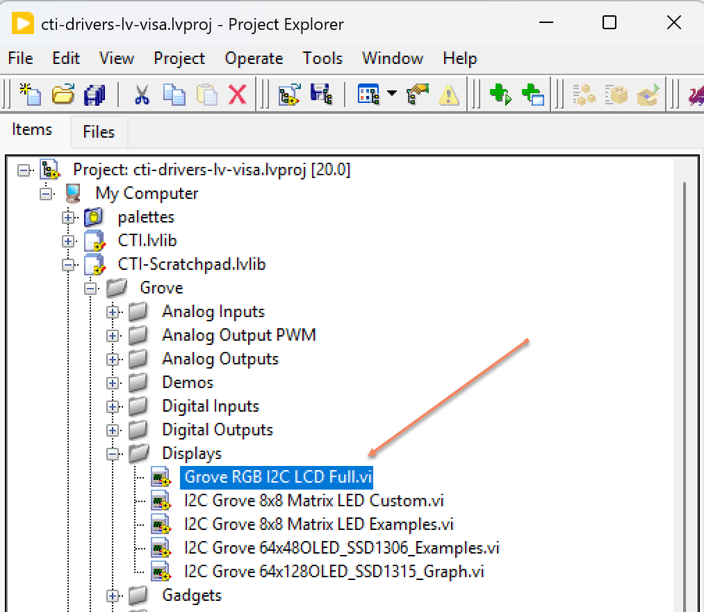
Navigate to >>Scratchpad>>Grove>>Displays>>Grove RGB I2C LCD Full.vi
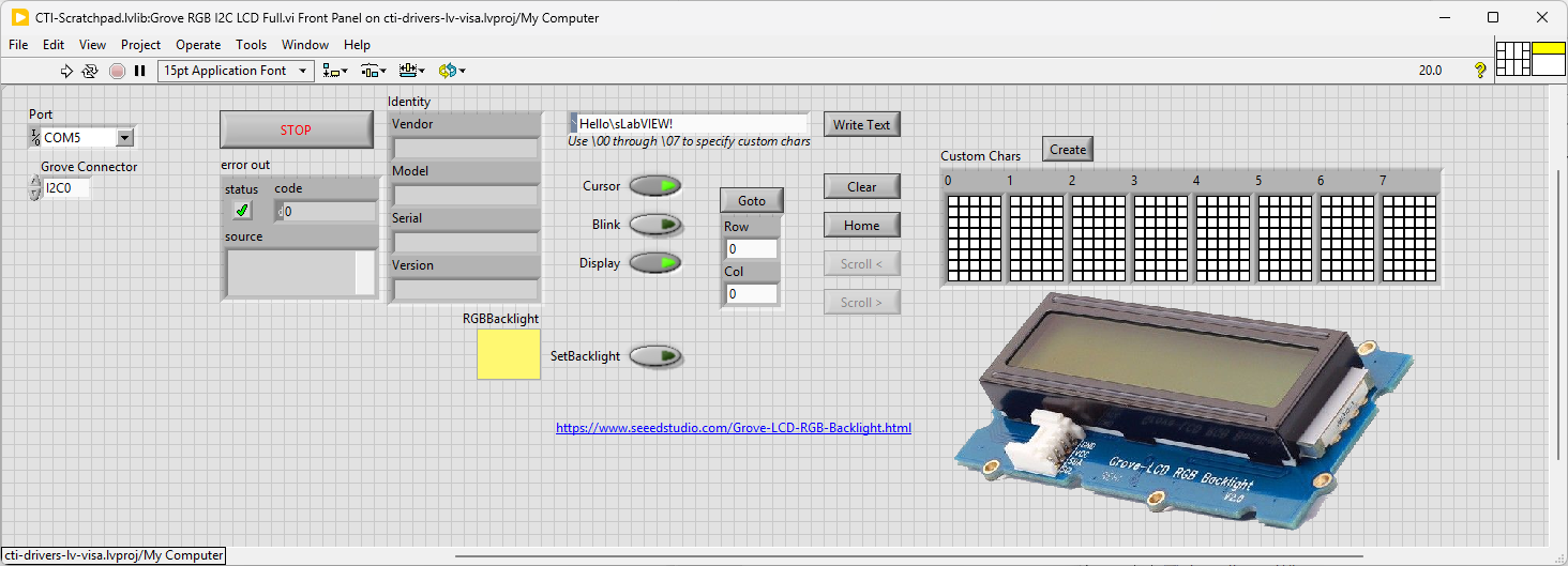
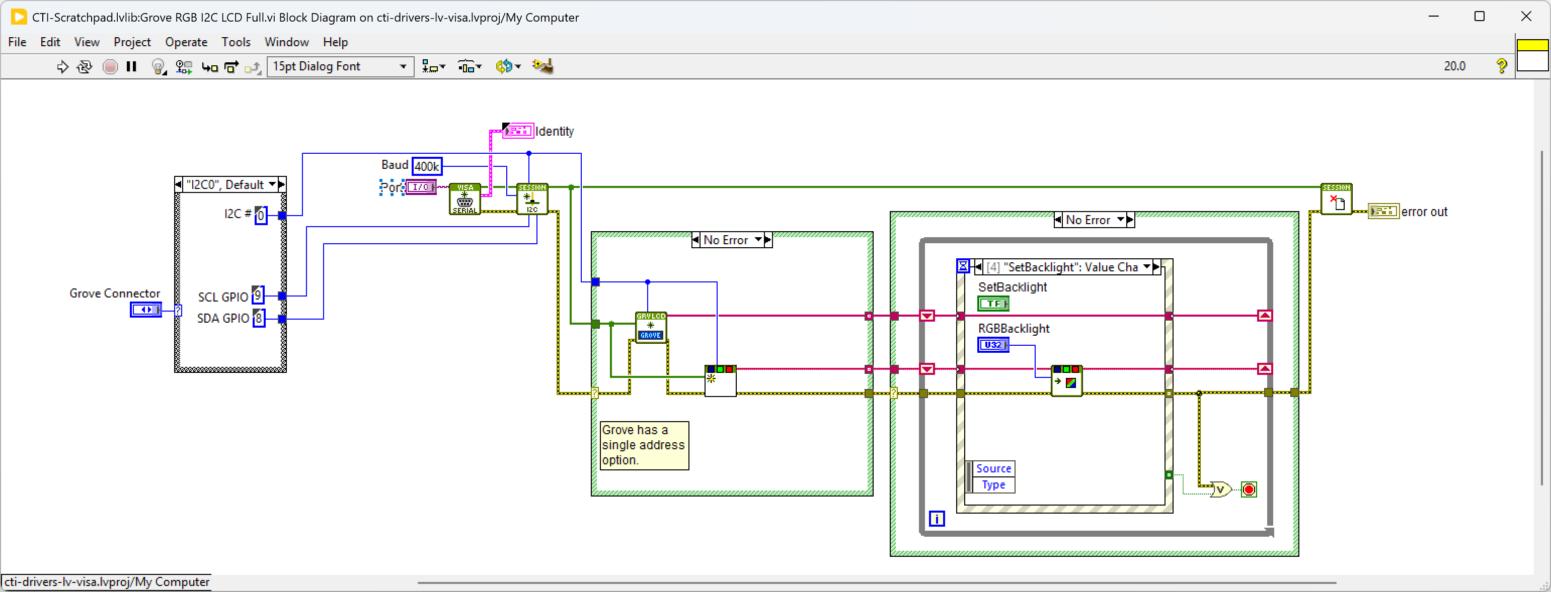
This VI uses sends text to the LCD display and also changes the backlight color. It communicates to 2 different I2C addresses to achieve this.
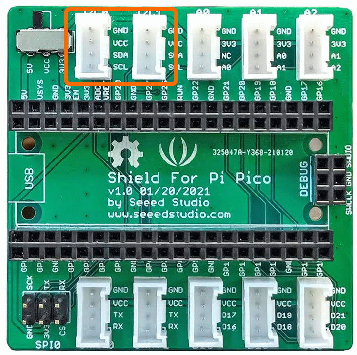
Select the port for the connected Pico and the Grove connector that the board is plugged into. Press the run arrow.
I’ve only implemented and tested the basic functionality for this board, so Write Text works, Clear and Home works and SetBacklight.
dictates the GPIO Pin for the IC2 Port. We set up the IC2 port for the device in Grove I2C LCD.lvclass:Init.vi and Grove I2C RGB SGM31323.lvclass:Init.vi. Next we loop round the event structure and wait for a button on the Front Panel to be pressed. When a button is detected (event:button>>Value Change will fire) the associated VI will run. Explore the different events to see how they operate. Pressing Stop will fire the Stop event and exit the loop.
SSD1315 64x128 OLED Display
Overview
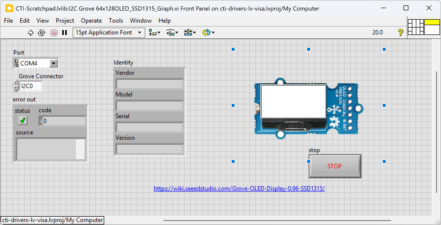
This example shows how to use a 2D picture control to display on a 64x128 monochrome OLED display
Demo Video
Here is a video that demonstrates how to use the 64x128 OLED display
And here’s the monochrome version
Example Code
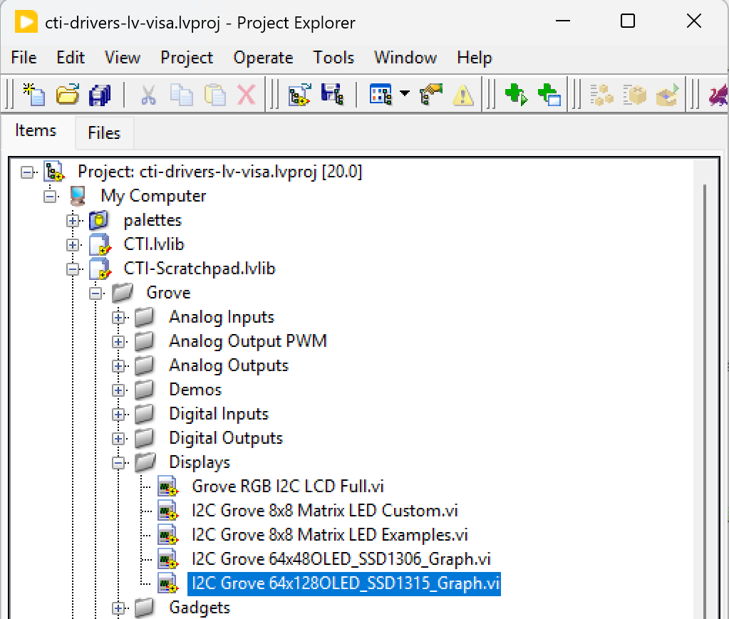
Navigate to >>Scratchpad>>Grove>>Displays>>I2C Grove 64x128OLED_SSD1315_Graph.vi
This particular VI builds a small graph image in a 2D picture control. This picture control is converted to a monochrome image and this image is converted into messages in I2C. Select the port for the connected Pico and the Grove connector that the board is plugged into. Press the run arrow.
You should see the graph fillng up with random numbers.
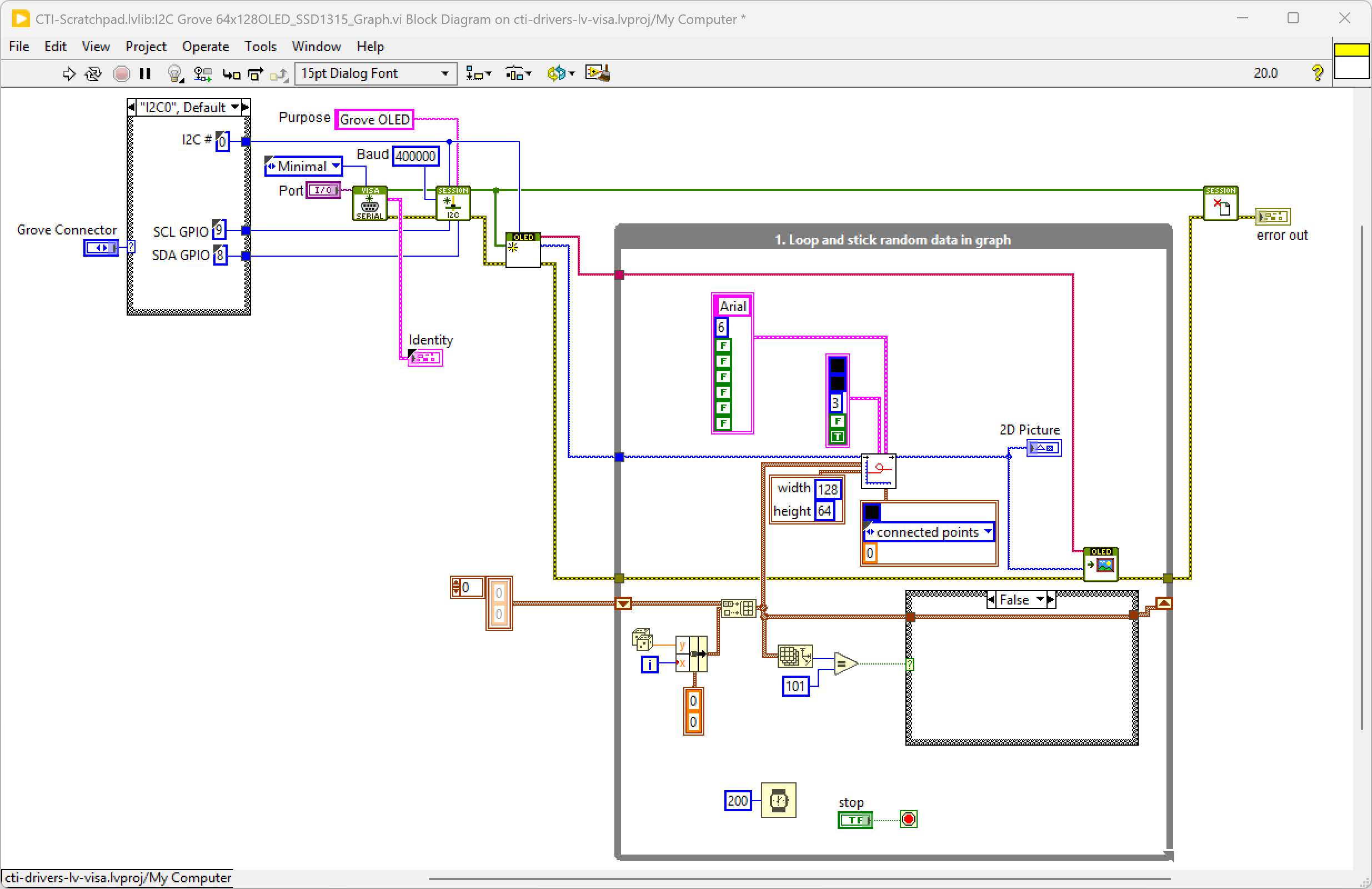
On the block diagram you can see that the selected Grove connector dictates the GPIO Pin used by the I2C port.
We set up the IC2 port for the device in 64x128 I2C OLED SSD1315.lvclass:Init.vi, this VI also outputs a picture of the correct dimensions as a template. The While Loop will now iterate every 200msecs adding a random number to the 100 element rolling buffer. This buffer is input to Plot XY.vi that creates the picture to fit our template. This picture is input into 64x128 I2C OLED SSD1315.lvclass:Write Image.vi that converts and transmits all the I2C messages.
Pressing Stop will exit the loop.
SSD1306 64x48 OLED Display
Overview
This example shows how to use a 2D picture control to display on a tiny monochrome OLED display
Example Code
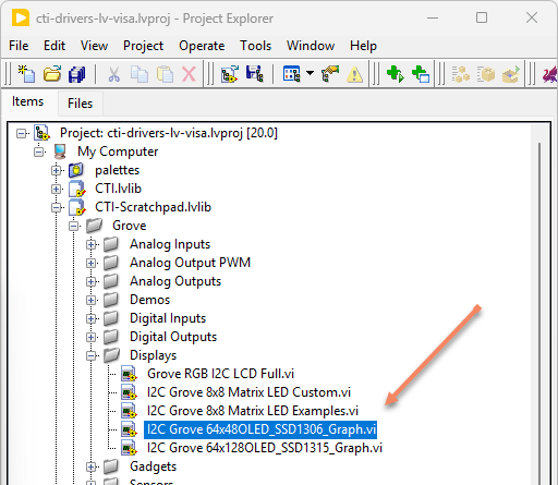
Navigate to >>Scratchpad>>Grove>>Displays>>I2C Grove 64x48OLED_SSD1306_Graph.vi
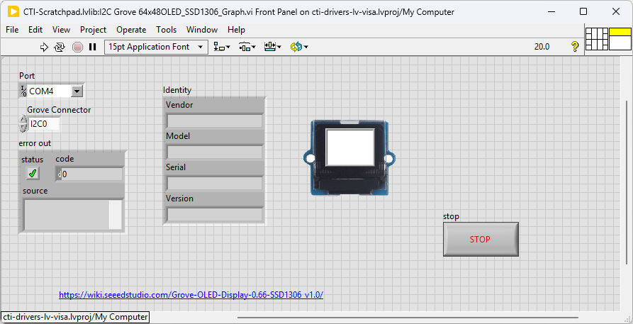
This particular VI builds a small graph image in a 2D picture control. This picture control is converted to a monochrome image and this image is converted into messages n I2C. Select the port for the connected Pico and the Grove connector that the board is plugged into. Press the run arrow.
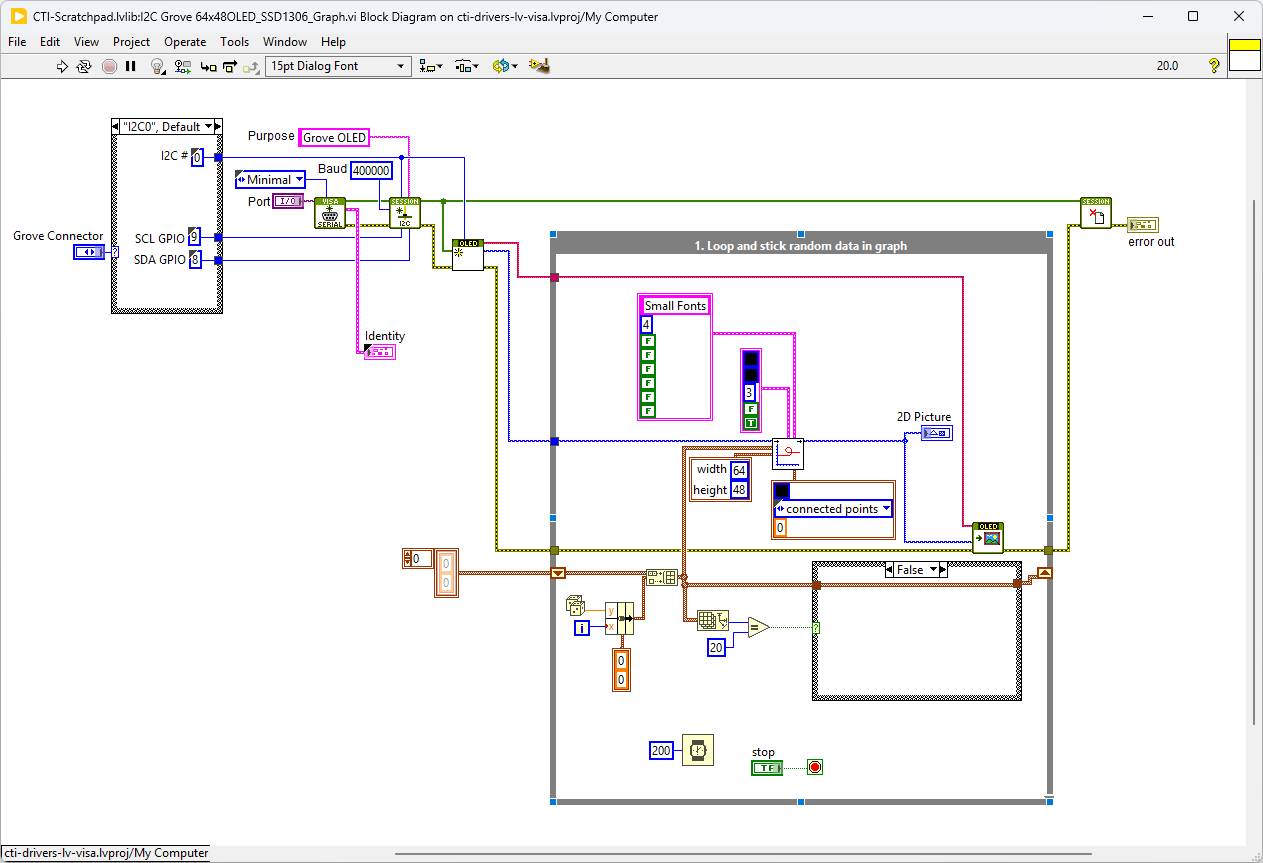
On the block diagram you can see that the selected Grove connector dictates the GPIO Pin used by the I2C port.
We set up the IC2 port for the device in 64x48 I2C OLED SSD1306.lvclass:Init.vi, this VI also outputs a picture of the correct dimensions as a template. The While Loop will now iterate every 200msecs adding a random number to the 100 element rolling buffer. This buffer is input to Plot XY.vi that creates the picture to fit our template. This picture is input into 64x48 I2C OLED SSD1306.lvclass:Write Image.vi that converts and transmits all the I2C messages.
Pressing Stop will exit the loop.
8x8 Matrix LED Driver (HT16K33)
Overview
The LED Matrix Driver board is low cost and usually used to display simple numbers and images. The Grove - LED Matrix Driver is the I2C based product which allows you to control the LED matrix. The 8*8 LED Matrix can be assembled and unassembled from the driver board easily, so it is convenient to change different color LED matrix display based on your need. The board can be set to 8 addresses allowing 8 boards to be run from a single I2C port.
Example Code
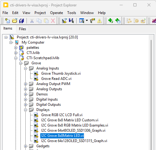
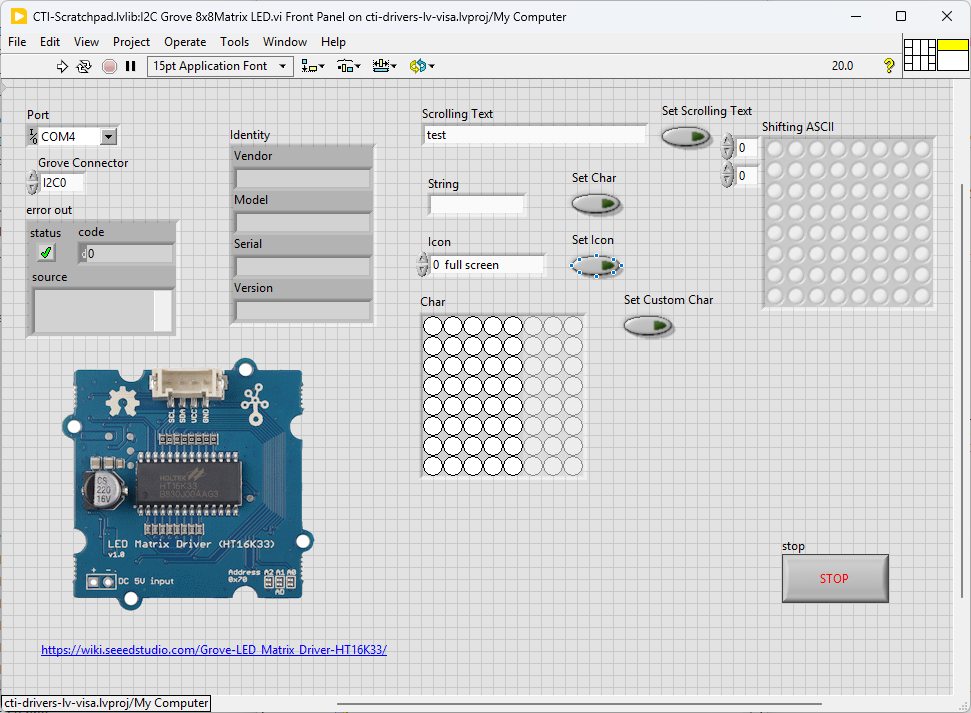
Navigate to >>Scratchpad>>Grove>>Displays>>I2C Grove 8x8Matrix LED.vi
Select the port for the connected Pico and the Grove connector that the board is plugged into. Press the run arrow.
Various pre-programed examples are available by selecting Set Scrolling Text, Set Char, Set Icon and Set Custom Char to display your chosen number or string.
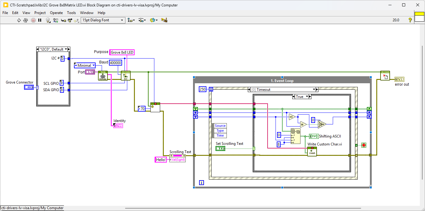
We set up the IC2 port for the device in Grove I2C Matrix LED Driver.lvclass:Init
On the block diagram you can see that the selected Grove connector dictates the GPIO Pin for the I2C Connector. Next we loop round an event structure and use the detect button value change events for Set Char, Set Icon or Set Custom Char. The fired event will use the associated data as an input to the selected function. In the timeout loop we can set or stop the scrolling function by toggling the Set Scrolling Text Button. The buffer is updated on a Scrolling Text Value change event.
Pressing Stop will fire the Stop event and exit the loop.
8x8 RGB Matrix LED
Overview
8x8 RGB LED Matrix is great for simple image display, 64 pixel leds and 255 colors for each pixel means almost infinite possibilities. However, the complicated wiring of the matrix is daunting. Now we present the Grove - RGB LED Matrix w/Driver for you, leave all the complex and variable wireing and soldering behind, just one single grove connector to control the RGB 8x8 LED matrix easily.
Example Code
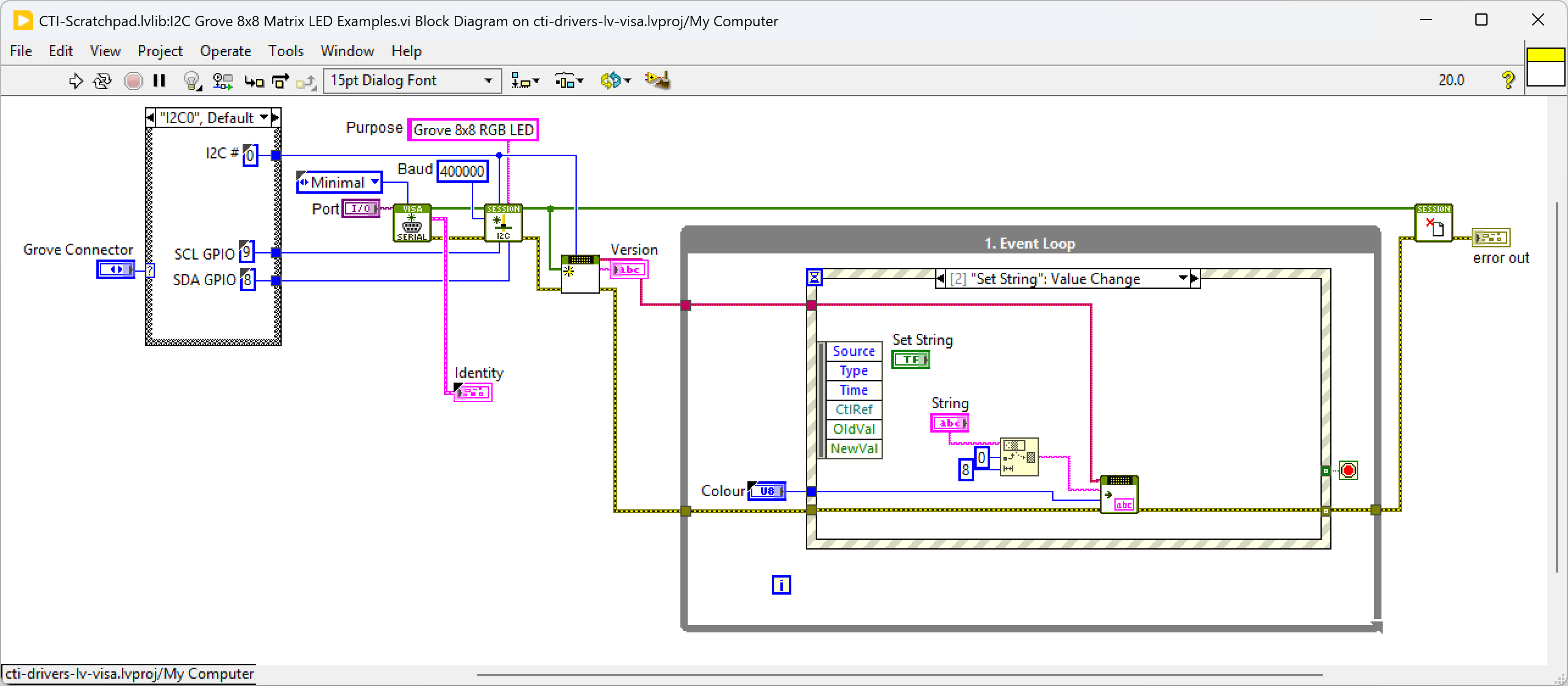
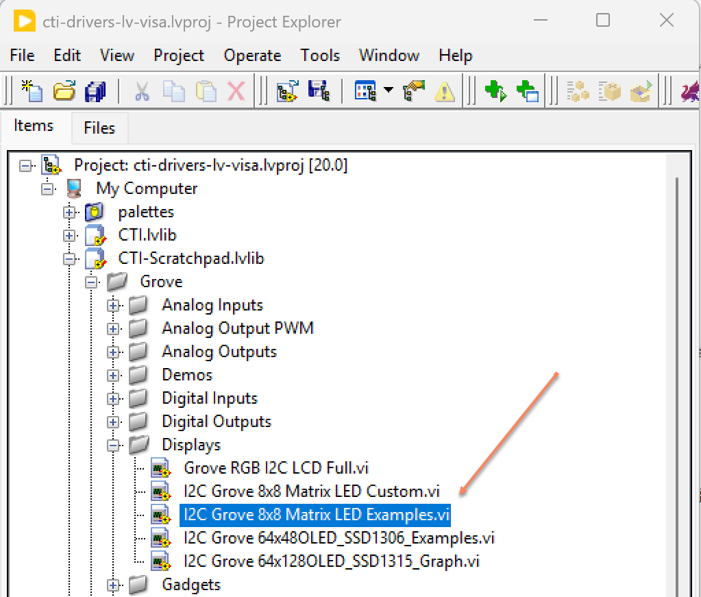
Navigate to >>Scratchpad>>Grove>>Displays>>I2C Grove 8x8 RGB Matrix LED Examples.vi
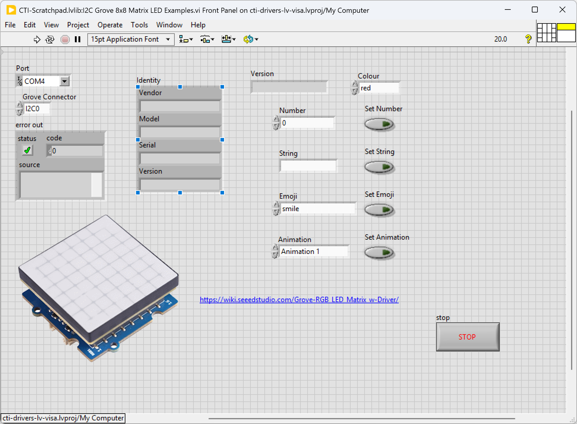
Select the port for the connected Pico and the Grove connector that the board is plugged into. Press the run arrow.
Various pre-programed examples are available by selecting the colour from the Colour enum and then pressing Set Number or Set String to display your chosen number or string.
Set Emoji or Set Animation will display your selected Emoji or Animation.
We set up the IC2 port for the device in Grove 2 RGB LED Matrix.lvclass:Init
On the block diagram you can see that the selected Grove connector dictates the GPIO Pin for the I2C Connector. Next we loop round an event structure and use the detect button value change events for Set Number, Set String, Set Emojo or Set Animation. The fired event will use the associated data as an input to the selected function.
Pressing Stop will fire the Stop event and exit the loop.