Grove Analog Inputs
Grove Standard Analog Inputs
Overview
An analog input can be thought of as a measurement or sensor reading. These will natively have a resolution of 12 bits, which can be thought of as a sensitivity across the range of the input. 12 bits= 4096 levels across the range.
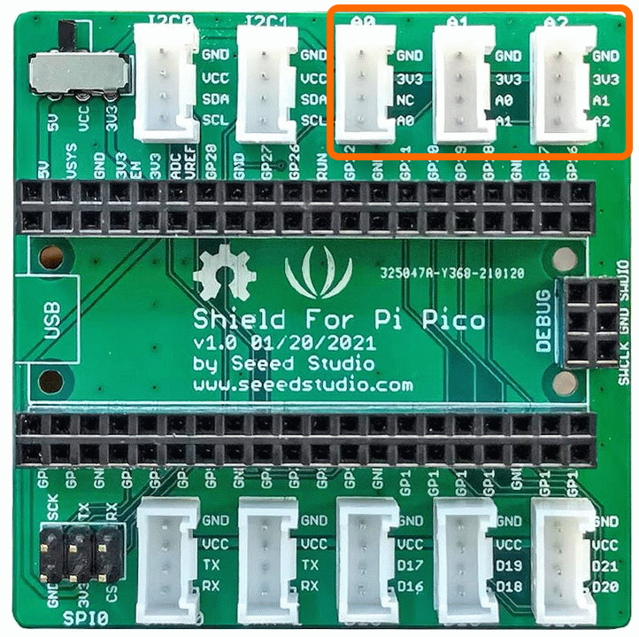
The Connections used are [A0,NC],[A0,A1],[A1,A2] and these correspond to GPIO Pins A0=GPIO26, A1=GPIO27, A1=GPIO28
The connectors used are [A0],[A1],[A2] as shown below
Example Code
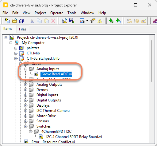
Navigate to >>Scratchpad>>Grove>>Analog Inputs>>Grove Read ADC.vi
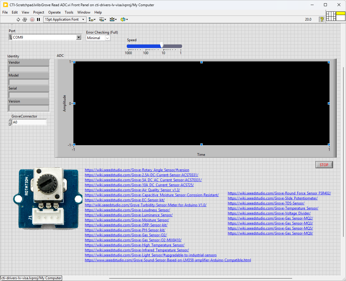
This particular VI uses a rotary angle sensor (potentiometer). Select the port for the connected Pico and the Grove connector that the board is plugged into. Press the run arrow.
You should be able to see the graph change corresponding to how much you change the rotary sensor.
Links to various other similar boards are also on the Front Panel.
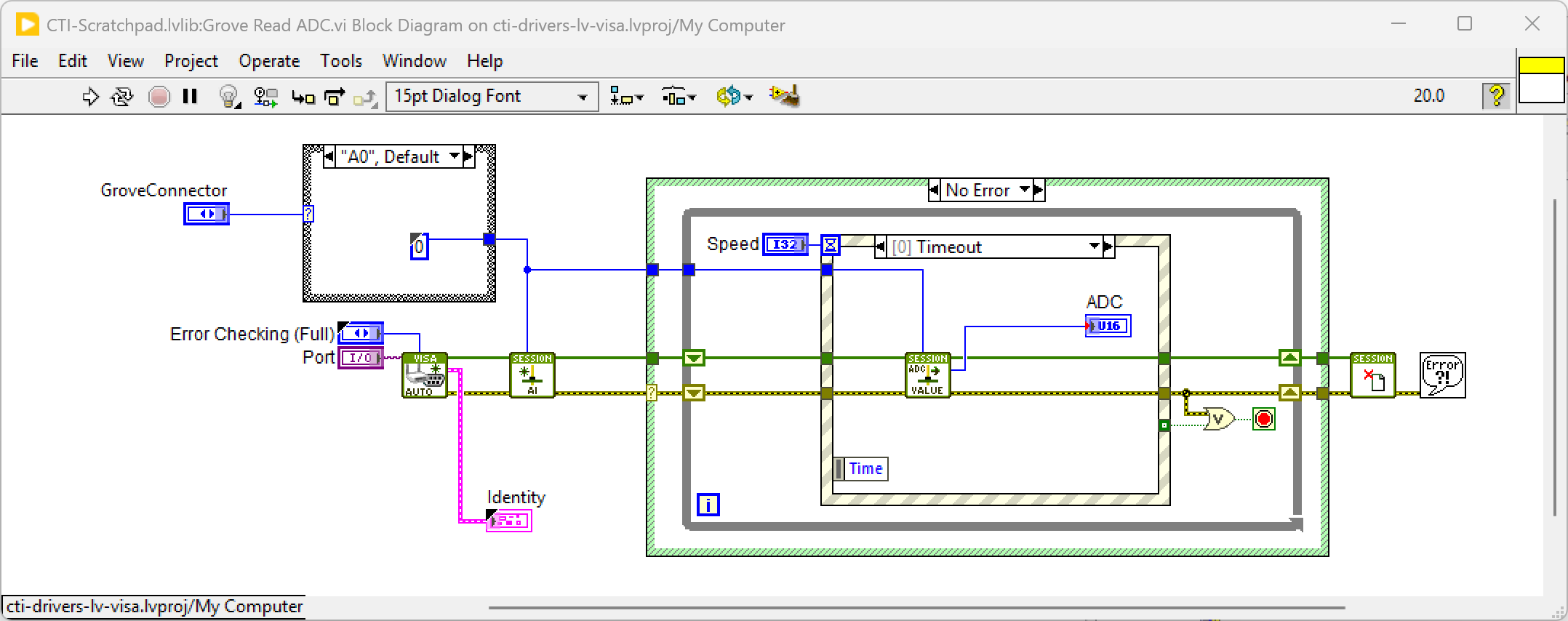
On the block diagram you can see that the selected Grove connector is input into Configure AI.vi. Next we loop round the event structure and use the timeout to poll the selected analog input using AI Read Value.vi. Pressing Stop will fire the Stop event and exit the loop.
Grove Thumb Joystick
Overview
Grove - Thumb Joystick is a Grove compatible module which is very similar to the 'analog' joystick on PS2 (PlayStation 2) controllers. The X and Y axes return a number between 0 and 4096 representing position.
The connectors used are [A1],[A2] as shown below because the joystick use 2 Analog Inputs. These correspond to GPIO Pins A1=GPIO27, A1=GPIO28

Example Code
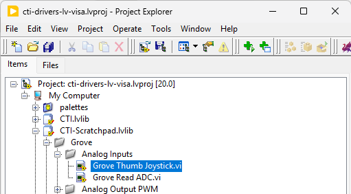
Navigate to >>Scratchpad>>Grove>>Analog Inputs>>Grove Thumb Joystick.vi
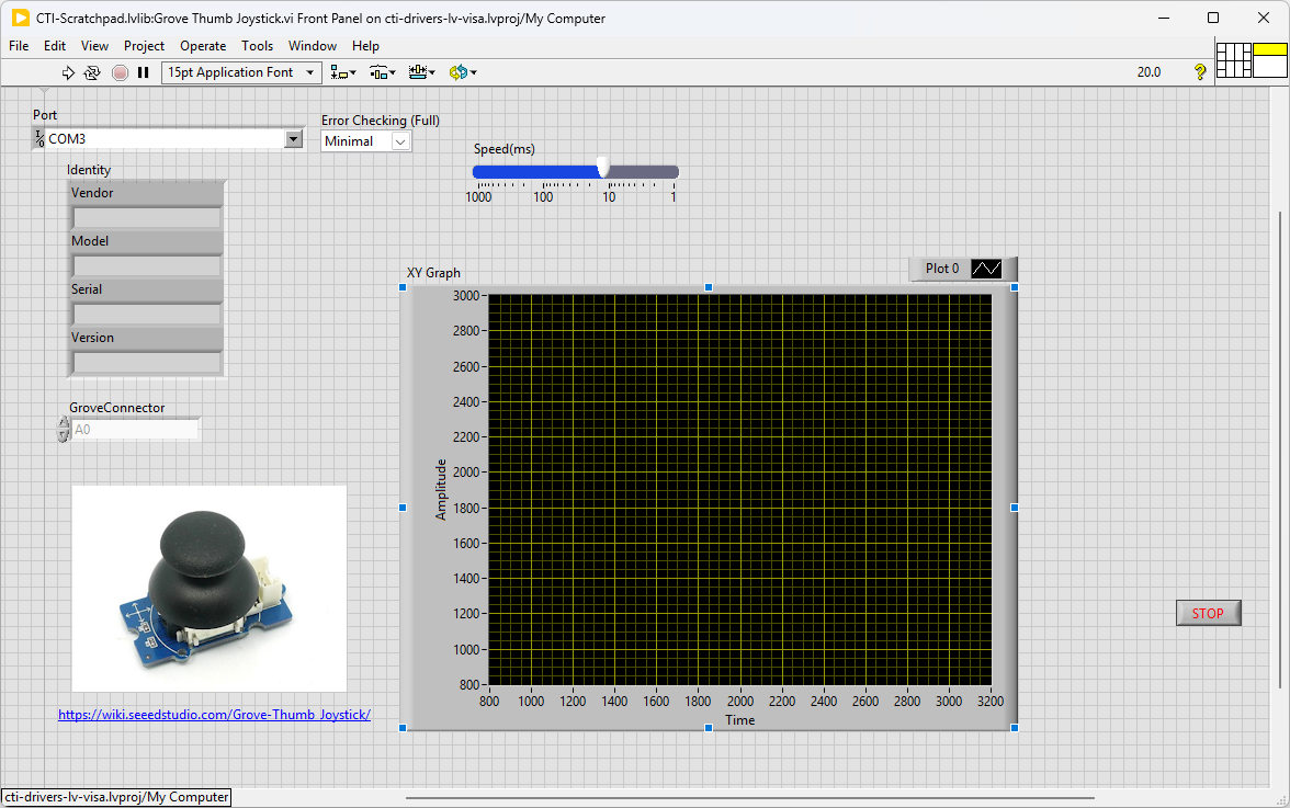
This particular VI uses a Grove Thumb Joystick. Select the port for the connected Pico and the Grove connector that the board is plugged into. Press the run arrow.
You should be able to see the graph change corresponding to how you steer the joystick.
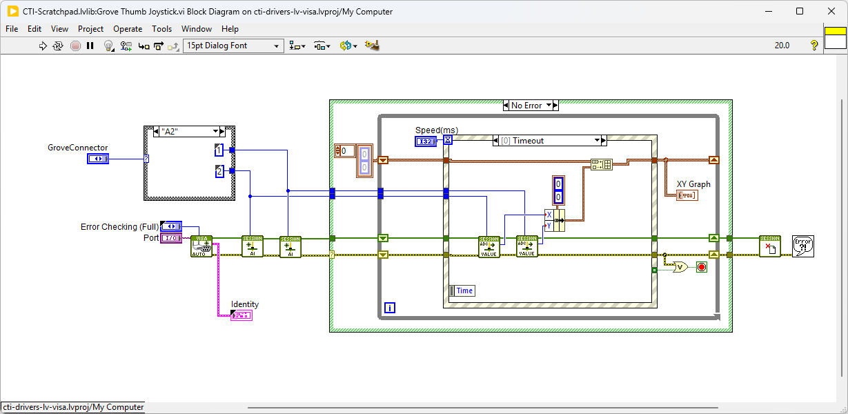
On the block diagram you can see that the selected Grove connector is input into 2 instances of Configure AI.vi. Next we loop round the event structure and use the timeout to poll the selected analog inputs using AI Read Value.vi. These value are displayed on an XY Graph. Pressing Stop will fire the Stop event and exit the loop.
Grove I2C Analog Inputs
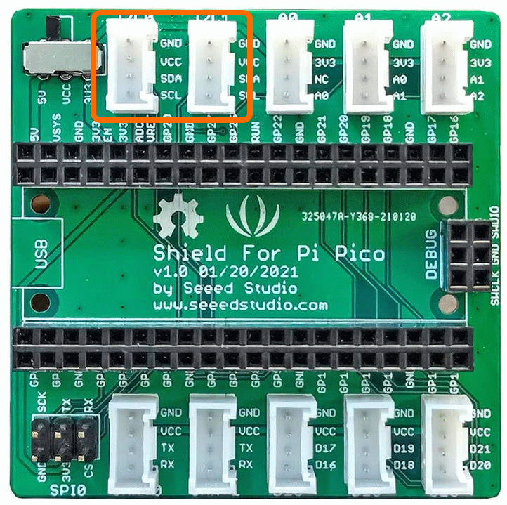
There are also options that communicate using I2C. These will use connectors I2C0 and I2C1 as shown. Commonly these will offer improved resolution e.g. 16 bits or 24 bits, so 65536 levels or 16,777,215 level respectively. They may also offer amplifiers, multiplexers or other enhanced functionality.
Grove I2C 4 Channel 16 Bit Analog Input
Demo Video
Here is a video that shows the set-up and running of the Grove I2C 4 Channel 16 Bit Analog Input module
Example Code
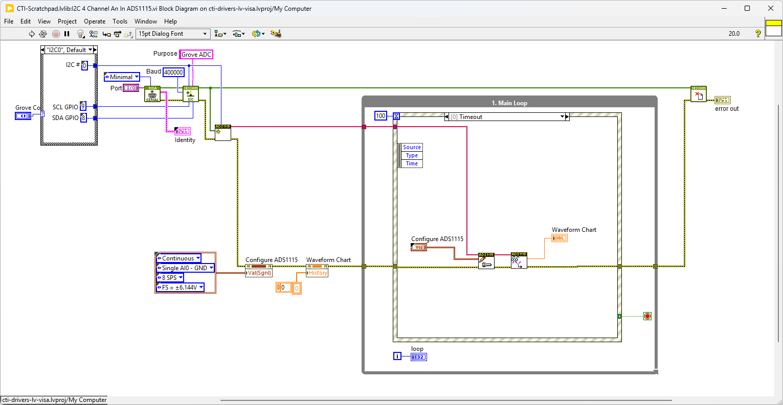
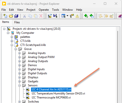
Navigate to >>Scratchpad>>Grove>>Sensors>>I2C 4 Channel An In ADS1115.vi
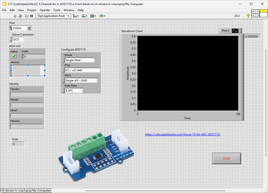
In this example we will need to have a voltage source to show a change in signal. Here I’ve just wired a potentiometer to the 5V and Ground on the board.
This VI uses ADS1115 4 Channels Analog Input Module. Select the port for the connected Pico and the Grove connector that the board is plugged into. Press the run arrow.
On the block diagram you can see that the selected Grove connector is input into Configure AI.vi. Next we loop round the event structure and use the timeout to poll the selected analog input using AI Read Value.vi. Pressing Stop will fire the Stop event and exit the loop.