Grove Analog Outputs
Standard Analog Output PWM
Overview
An analog output can be thought of as a way of generating a signal, the standard way this is done on a Pico is using a PWM square-wave.
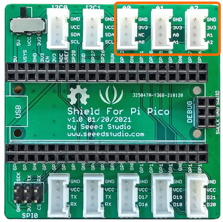
The Connections used are [A0,NC],[A1,A2],[A2,A1] and these correspond to GPIO Pins A0=GPIO26, A1=GPIO27, A1=GPIO28
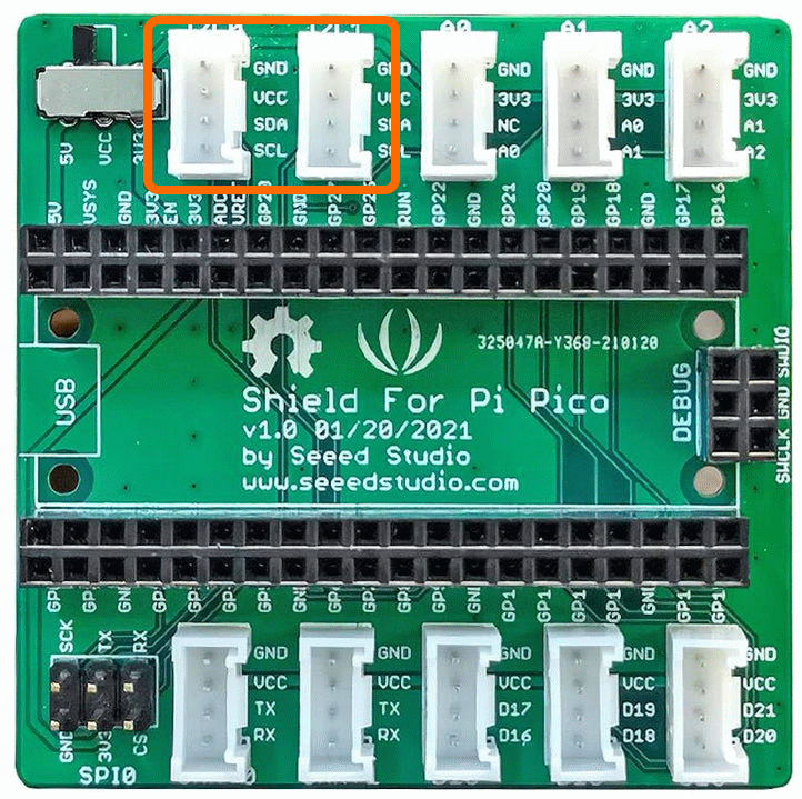
The connectors used are [A0],[A1],[A2] as shown below
This example uses the passive buzzer module but the source code is also applicable for other similar Grove Modules.
Demo Video
Here is a video that shows the set-up and running of the Passive buzzer using a piano scale to demonstrate Frequency and Duty Cycle
Example Code
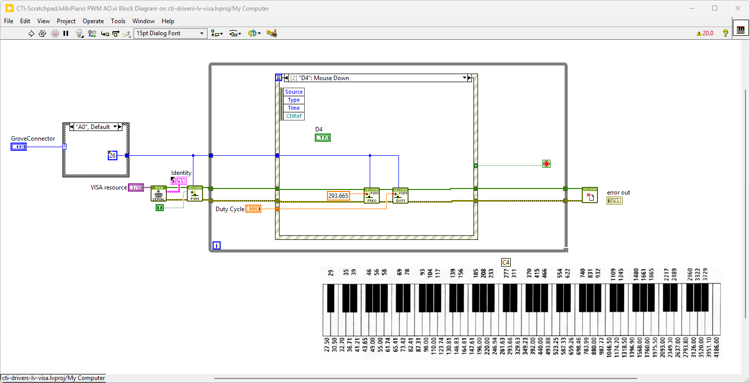
Navigate to >>Scratchpad>>Grove>>Analog Output PWM>>Piano PWM AO.vi
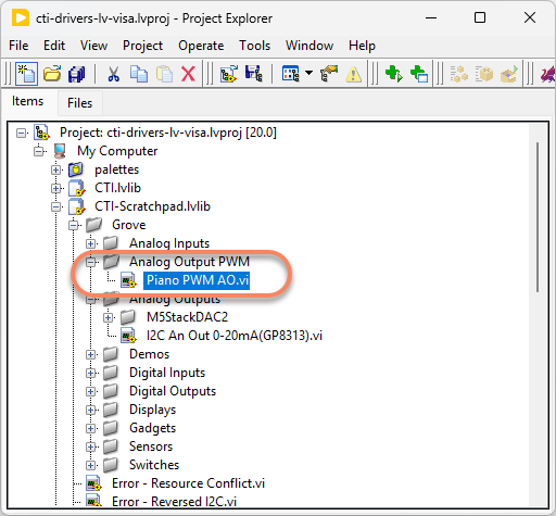
This particular VI uses the passive buzzer to make the sound. Select the port for the connected Pico and the Grove connector that the board is plugged into. Press the run arrow.
Links to various other similar boards are also on the Front Panel.
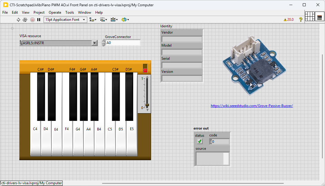
On the block diagram you can see that the selected Grove connector dictates the GPIO Pin and we then wire it to the Configure PWM.vi . Next we loop round the event structure waiting for button press events. If a piano key is pressed the corresponding frequency will be entered into the PWM Write Frequency.vi. If the duty cycle is high enough a sound of the right key should be heard. Pressing Stop will fire the Stop event and exit the loop.
M5Stack DAC2 I2C Analog Outputs
There are also options that communicate using I2C. These will use connectors I2C0 and I2C1 as shown. Commonly these will offer improved resolution e.g. 16 bits so 65536 levels. They may also offer amplifiers, multiplexers or other enhanced functionality.
Overview
This example uses the M5Stack DAC 2 Module, there are other similar modules that may work with this code as it uses the GP8313 integrated circuit. These are Grove compatible modules.
The GPIO Pins used are [I2C0] or [I2C1]
Example Code
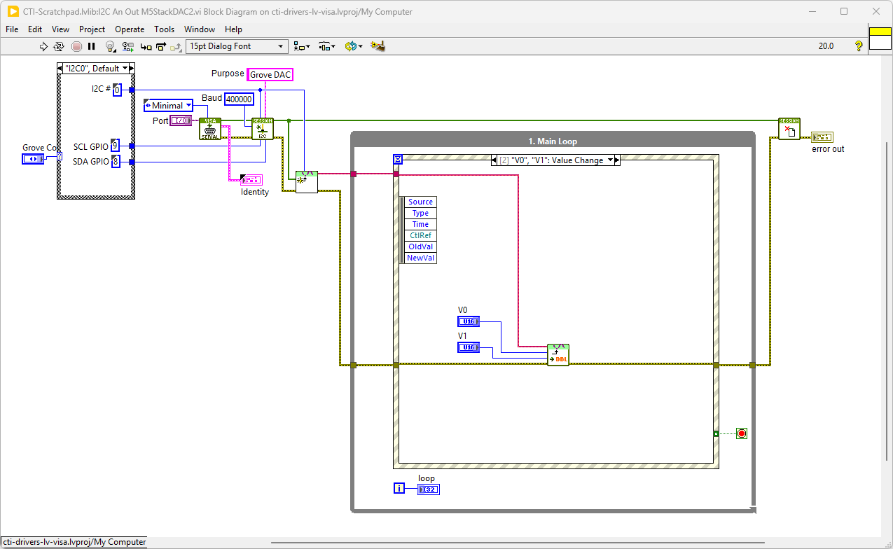
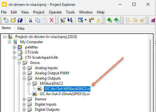
Navigate to >>Scratchpad>>Grove>>Analog Outputs>>I2C An Out M5StackDAC2.vi
This particular VI uses the M5Stack DAC2 and this gives us 2 channels of 16 bit Analog Output. Select the port for the connected Pico and the Grove connector that the board is plugged into. Press the run arrow.
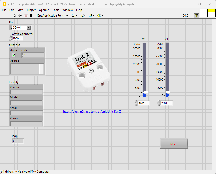
On the block diagram you can see that the selected Grove connector dictates the GPIO Pin for the IC2 Port. We set up the IC2 port for the device in Init.vi. Next we loop round the event structure and wait for a Sliders V0 or V1 to be changed. When change has been detected the new values are input into the Write DAC.vi. Pressing Stop will fire the Stop event and exit the loop.