Sensors
Grove has a wide variety of sensors that can be communicated to using I2C.
Grove I2C Sensors
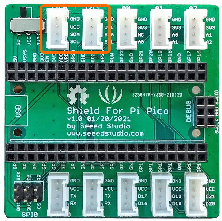
There are also options that communicate using I2C. These will use connectors I2C0 and I2C1 as shown. Commonly these will offer improved resolution e.g. 16 bits or 24 bits, so 65536 levels or 16,777,215 level respectively. They may also offer amplifiers, multiplexers or other enhanced functionality.
Grove I2C Temperature Humidity Sensor DH20
Overview
The Grove - Temperature & Humidity Sensor is based on the DHT20 sensor. The DH20 is an upgraded version of the DHT11, compared with the previous version, the temperature and humidity measurement accuracy are higher, and the measurement range is larger. It features I2C output which means it is easier to use.
Demo Video
Here is a video that shows the set-up and running of the Grove I2C Temperature Humidity Sensor
Example Code
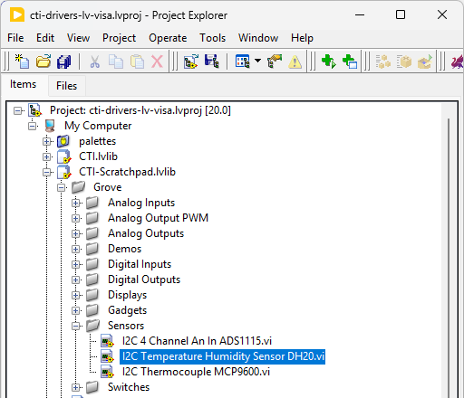
Navigate to >>Scratchpad>>Grove>>Sensors>>I2C Temperature Humidity Sensor DH20.vi
This VI uses Grove I2C Temperature Humidity DH20 Sensor. Select the port for the connected Pico and the Grove connector that the board is plugged into. Press the run arrow.
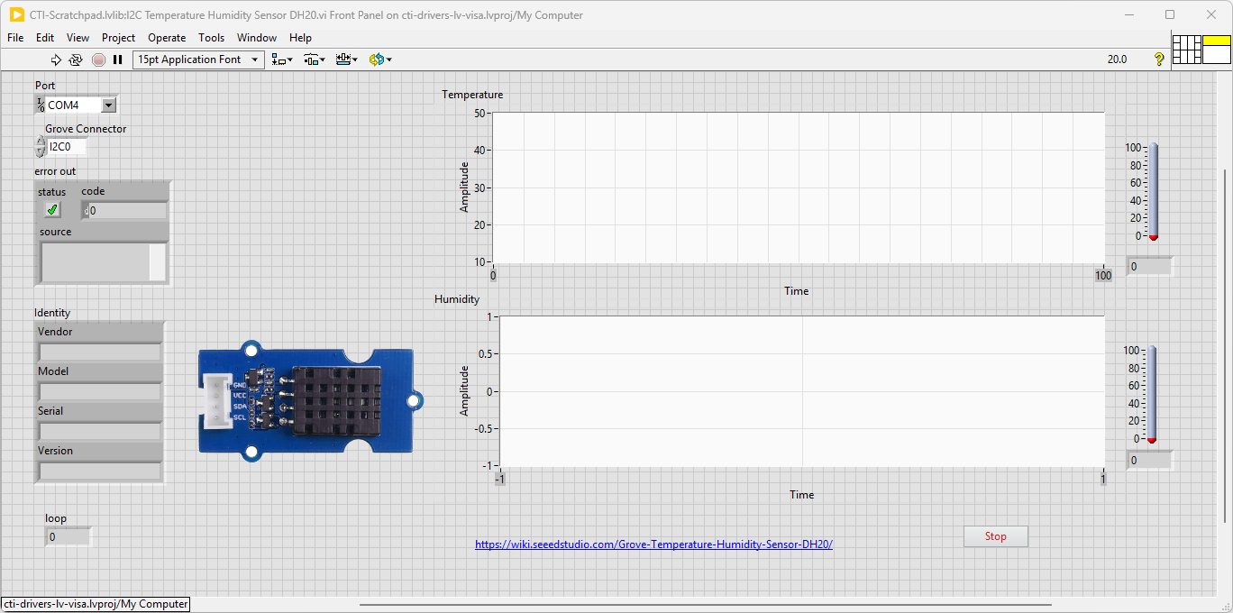
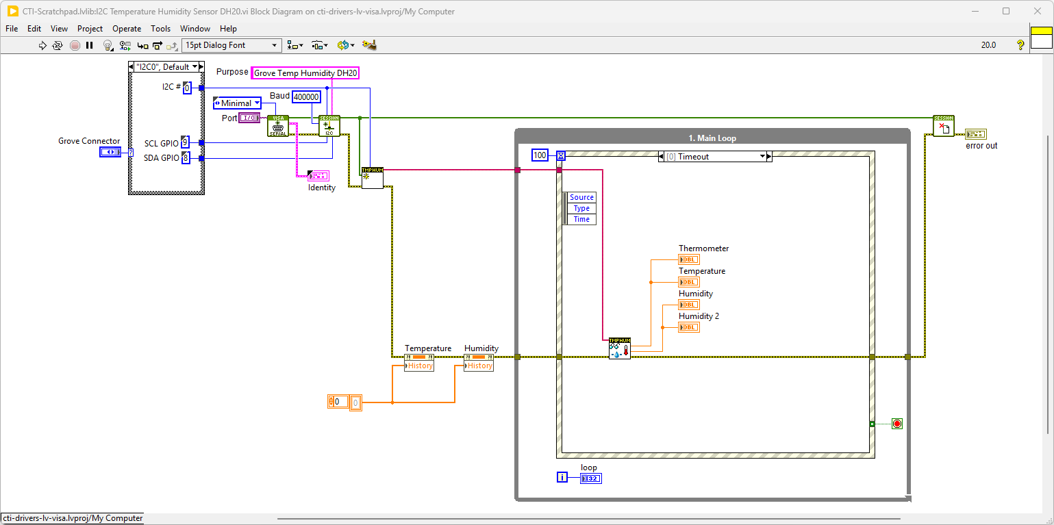
On the block diagram you can see that the selected Grove connector is input into Grove Temperature Humidity Sensor DH20.lvclass:Init.vi. Next we loop round the event structure and use the timeout to poll the Sensors using Grove Temperature Humidity Sensor DH20.lvclass:Read Temp Humidity.vi. Pressing Stop will fire the Stop event and exit the loop.
Grove I2C Thermocouple Sensor
Overview
The Grove - I2C Thermocouple Amplifier (MCP9600) is a thermocouple-to-digital converter with integrated cold-junction and I2C communication protocol. This module is designed to be used in conjunction with a k-type thermocouple. The thermocouples have a much larger measurement range than thermistors.
Demo Video
Here is a video that shows the set-up and running of the Grove I2C Thermocouple Amplifier MCP9600
Example Code
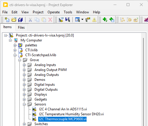
Navigate to >>Scratchpad>>Grove>>Sensors>>I2C Thermocouple MCP9600.vi
This VI uses Grove I2C Thermocouple Amplifier MCP9600. Select the port for the connected Pico and the Grove connector that the board is plugged into. Press the run arrow.
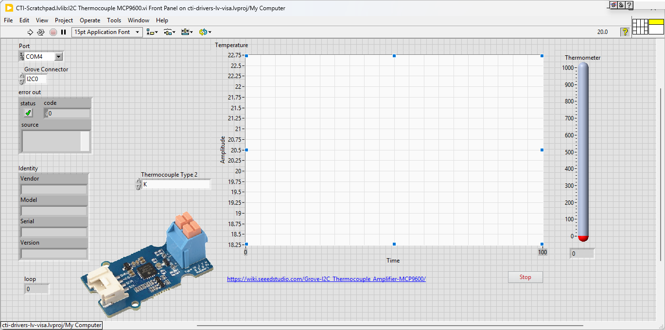
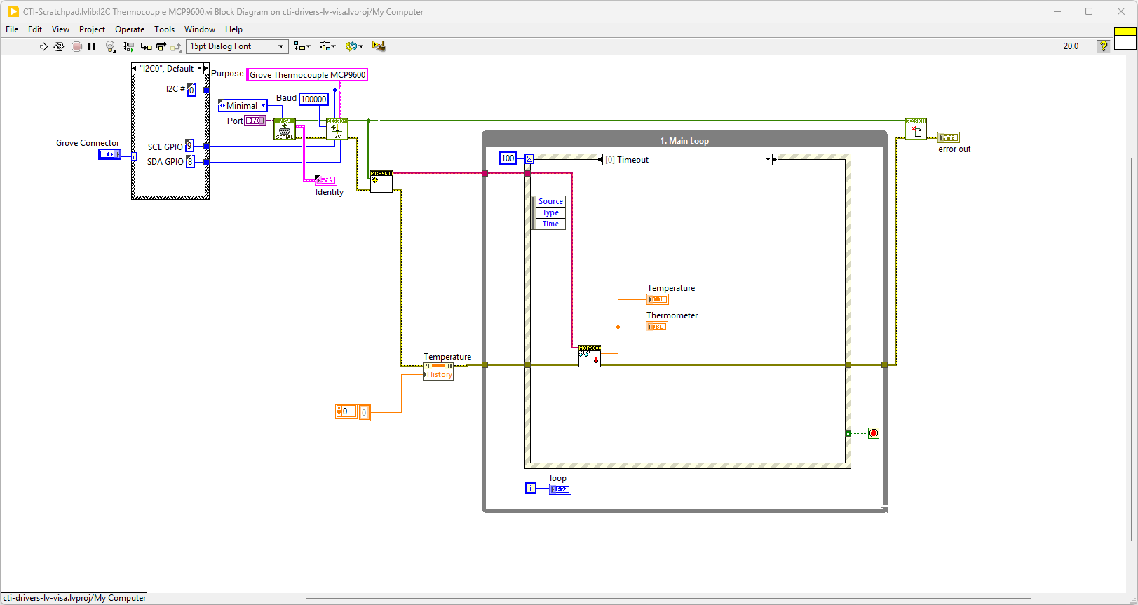
On the block diagram you can see that the selected Grove connector is input into Grove Thermocouple MCP9600.lvclass:Init.vi. We then can set the thermocouple type from the Thermocouple Type Value Change event and Grove Thermocouple MCP9600.lvclass:Set Thermocouple Type.vi. Next we loop round the event structure and use the timeout to poll the Sensors using Grove Thermocouple MCP9600.lvclass:Read Temperature.vi. Pressing Stop will fire the Stop event and exit the loop.
Adafruit NAU7802 I2C Strain Gauge Module
Overview
A strain gauge (also spelled strain gage) is a device used to measure strain on an object. Invented by Edward E. Simmons and Arthur C. Ruge in 1938, the most common type of strain gauge consists of an insulating flexible backing which supports a metallic foil pattern. As the object is deformed, the foil is deformed, causing its electrical resistance to change. This resistance change, usually measured using a Wheatstone bridge, is related to the strain by the quantity known as the gauge factor.
From Wikipedia
Hardware Details
The NAU7802 module contains a super-high-resolution 24-Bit differential ADC with extra gain and calibration circuitry that makes it perfect for measuring strain gauges / load cells or other sensors that have four wires that are connected in a Wheatstone bridge arrangement.
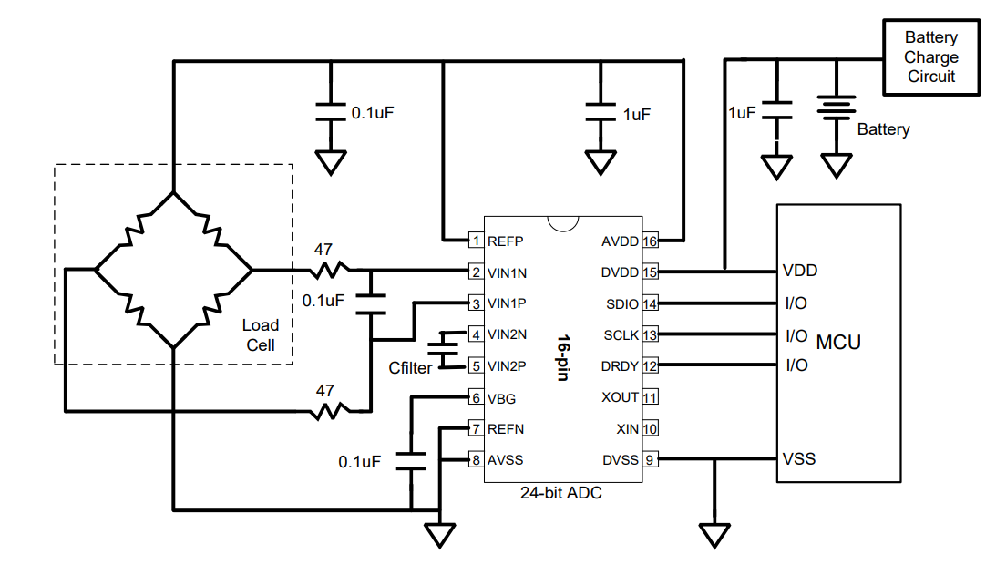
Each breakout comes with a NAU7802 ADC chip, plus some support circuitry, and 4 terminal blocks that can be used to connect a 4-wire sensor.
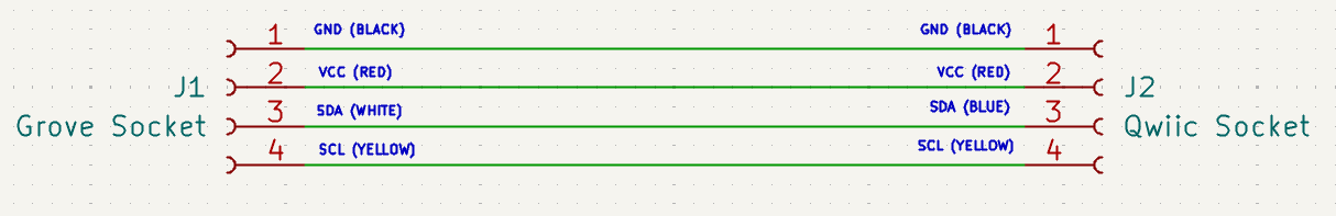
This board uses the Qwiic connector, so we will need to use a Qwiic to Grove lead.. These can be bought directly or made to the circuit diagram below.
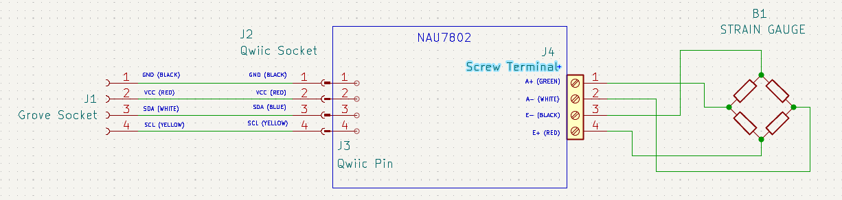
The wiring diagram for the board will therefore look like this.
Demo Video
Here is a video that shows the set-up and running of the Adafruit NAU7802 I2C Strain Gauge Module
Example Code
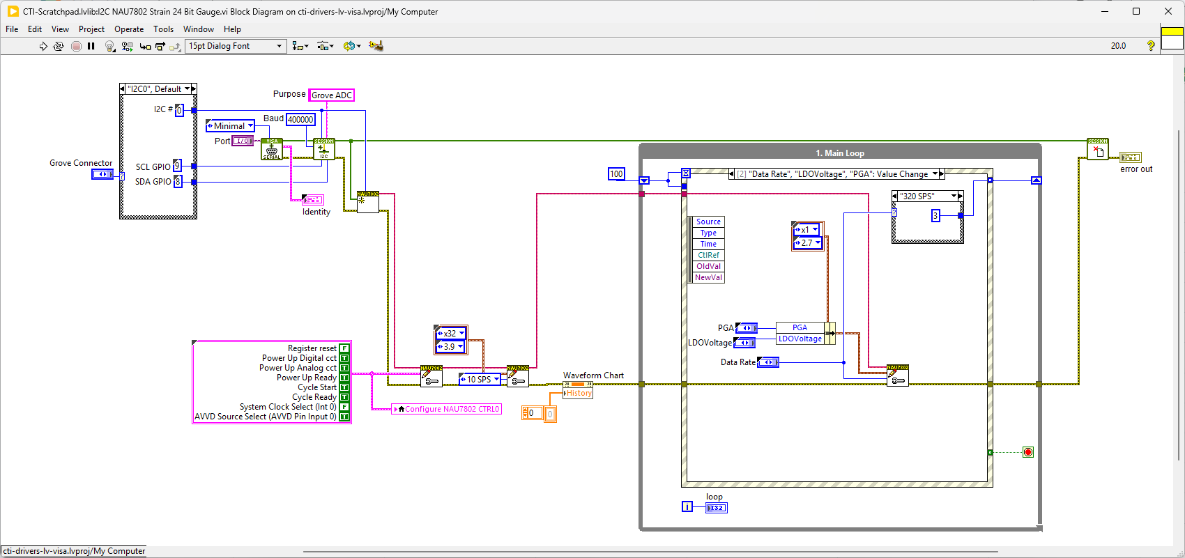
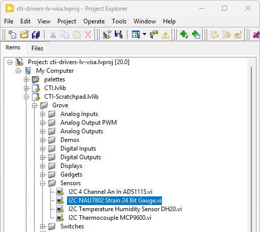
Navigate to >>Scratchpad>>Grove>>Sensors>>I2C NAU7802 Strain 24 Bit Gauge.vi
This VI uses NAU7802 Strain Gauge IC. Select the port for the connected Pico and the Grove connector that the board is plugged into. Press the run arrow.
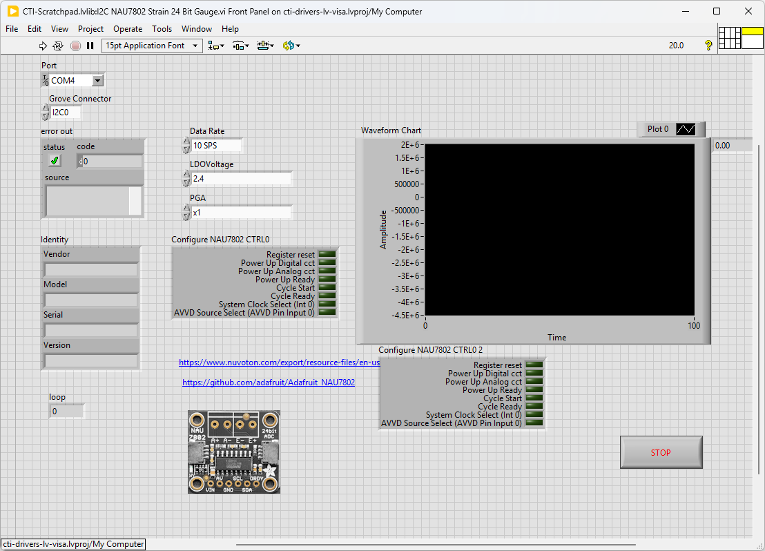
On the block diagram you can see that the selected Grove connector is input into Adafruit NAU7802 24bit Strain Gauge.lvclass:Init.vi. We then can set PU_CTRL Register to start measuring using Adafruit NAU7802 24bit Strain Gauge.lvclass:Set PU_CTRL.vi and set up the ADC using Adafruit NAU7802 24bit Strain Gauge.lvclass:Set ADC.vi Next we loop round the event structure and use the timeout to poll the Sensors using Adafruit NAU7802 24bit Strain Gauge.lvclass:Read PU_CTRL.vi if the Cycle Ready bit is high it means there is a reading available. The timeout of the event loop is adjusted to suit the Samples Per Second. If a reading is available we get the 24 bits using Adafruit NAU7802 24bit Strain Gauge.lvclass:Read ADC.vi. Pressing Stop will fire the Stop event and exit the loop.