Grove Digital Inputs
Standard Digital Input
Overview
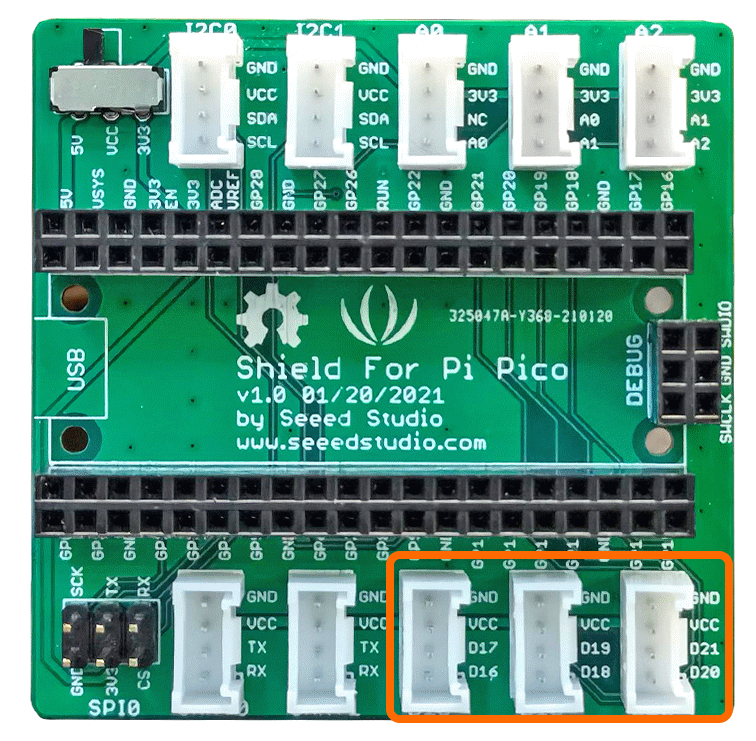
A digital input can be thought of as the reading from a button, a switch or a digital sensor. These examples use the GPIO Pins [D16,D17],[D18,D19],[D20,D21] that correspond to connectors D16,D18 and D20 on the grove hat.
This example uses the grove button module but the source code is also applicable for other similar Grove Modules.
Example Code
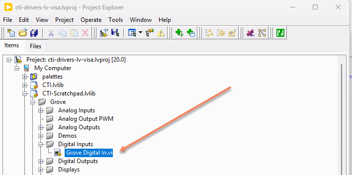
Navigate to
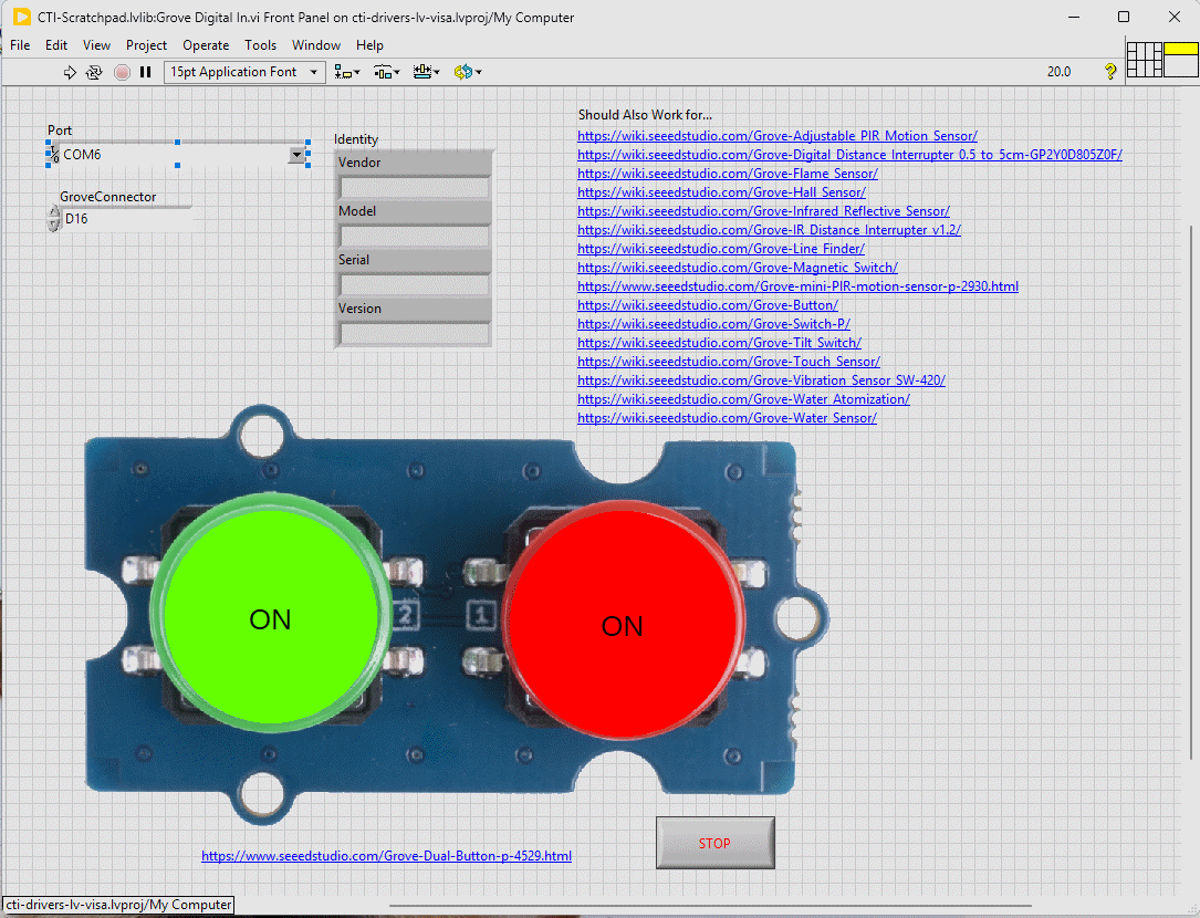
This particular VI uses the dual buttons. Select the port for the connected Pico and the Grove connector that the board is plugged into. Press the run arrow.
You should now see the button indicators light up when the corresponding button is pressed. The Indicators use a transparent fill for the off state and a brighter Red or Green for the on state.
Links to various other similar boards are also on the Front Panel.
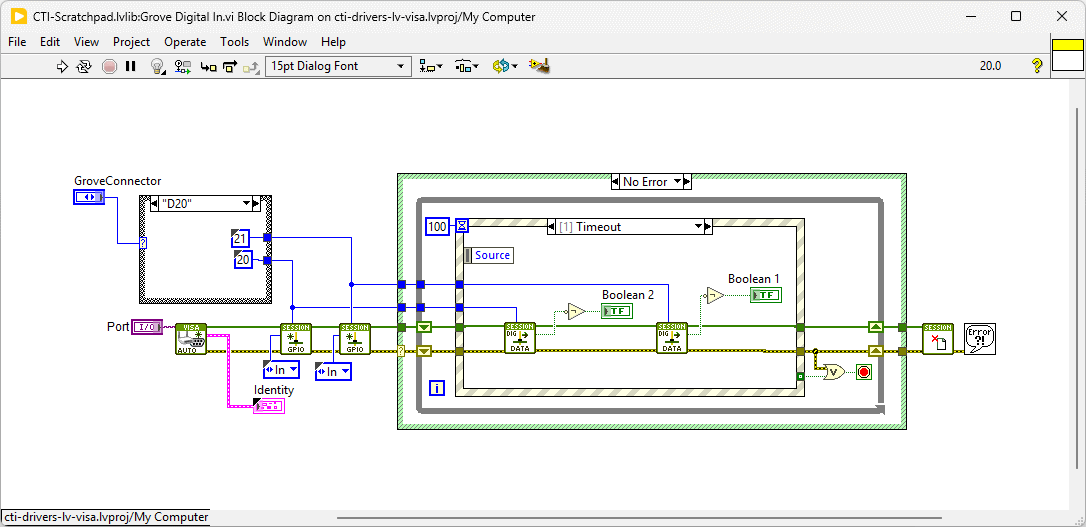
On the block diagram you can see that the selected Grove connector dictates the GPIO Pin and we then set the pin to [In]. Next we loop round and event structure and use the timeout to poll the digital inputs. Pressing Stop will fire the Stop event and exit the loop.