Grove Digital Outputs
Standard Digital Output
Overview
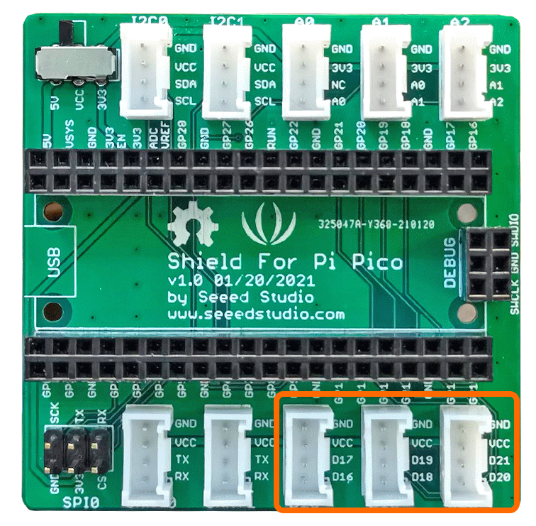
A digital output can be thought of as the signal to an LED or a relay. These examples use the GPIO Pins [D16,D17],[D18,D19],[D20,D21] that correspond to connectors D16,D18 and D20 on the grove shield.
Demo Video
Here is a video that shows the set-up and running of the LED and Relay Examples
This video demonstrates the Electro-Magnet, using the Grove Digital Out Switch.vi
Example Code
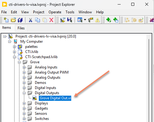
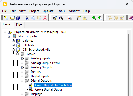
Navigate to >>Scratchpad>>Grove>>Digital Inputs>>Grove Digital Out.vi or Grove Digital Out Switch.vi
These examples are very similar
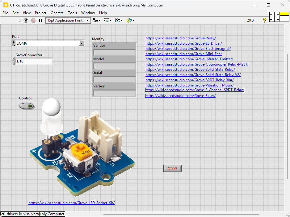
This particular VI uses the Green LED. Select the port for the connected Pico and the Grove connector that the board is plugged into. Press the run arrow.
When you press the [Control Button] the LED should toggle on and off.
Links to various other similar boards are also on the Front Panel.
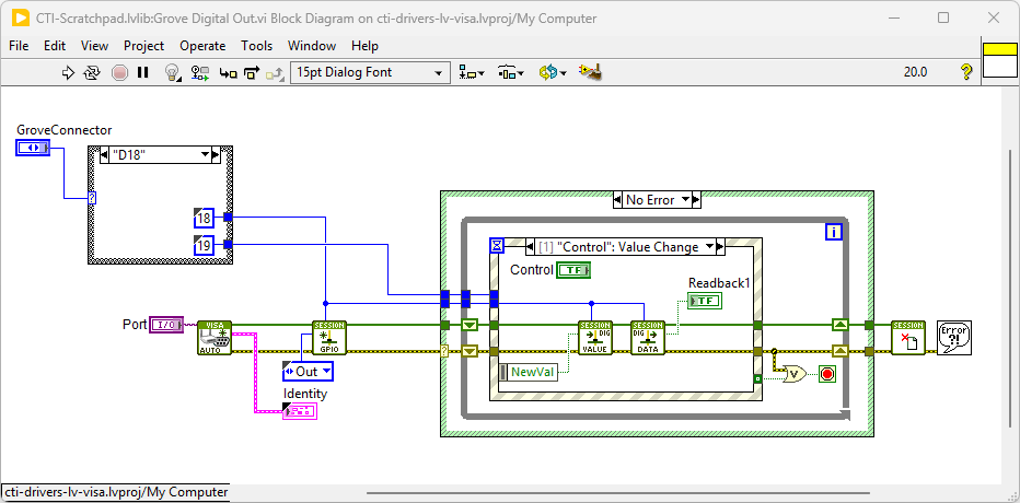
On the block diagram you can see that the selected Grove connector dictates the GPIO Pin and we then set the pin to [Out]. Next we loop round and event structure and use the Control Value Change Event to set the LED. Pressing Stop will fire the Stop event and exit the loop. The video also shows the same VI being used to switch a relay on and off.
SPST Relay Board / MOSFET Switch
Overview
This is essentially the same VI as the LED output VI, but with different graphics. There are some demo videos just to show wiring and operation.
I2C 4 Channel SPDT Relay Board
Overview
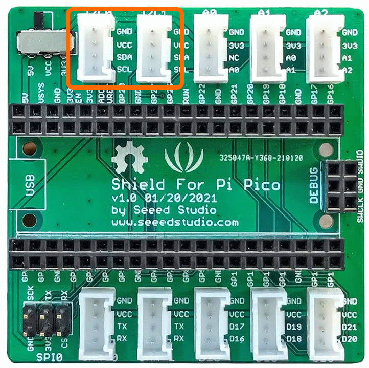
There are also options that communicate using I2C. These will use connectors I2C0 and I2C1 as shown.
This example uses the grove 4 Channel Relay module, there are other similar modules that may work with this code.
The Single Pole Double Throw SPDT relay is quite useful in certain applications because it has one common terminal and 2 contacts which are great for selecting between two options. The Grove - 4-Channel SPDT Relay has four single pole - double throw (SPDT) switches. It only requires low-voltage and low current signals to control those switches. Specifically, you can use 5V DC to control max.250V AC or 110V DC. The I2C address is changeable so that you can use multiple relay modules in the same project. The Grove - 4-Channel SPDT Relay has four single pole - double throw (SPDT) switches. It only requires low-voltage and low current signals to control those switches. Specifically, you can use 5V DC to control max.250V AC or 110V DC.
SEEED uses an on-board STM32F030F4P6 to control the channels separately. The command from Arduino or other boards is transmit via the I2C interface, the on-board STM32F030F4P6 will parse the command, so that you can control the switch you want.
Example Code
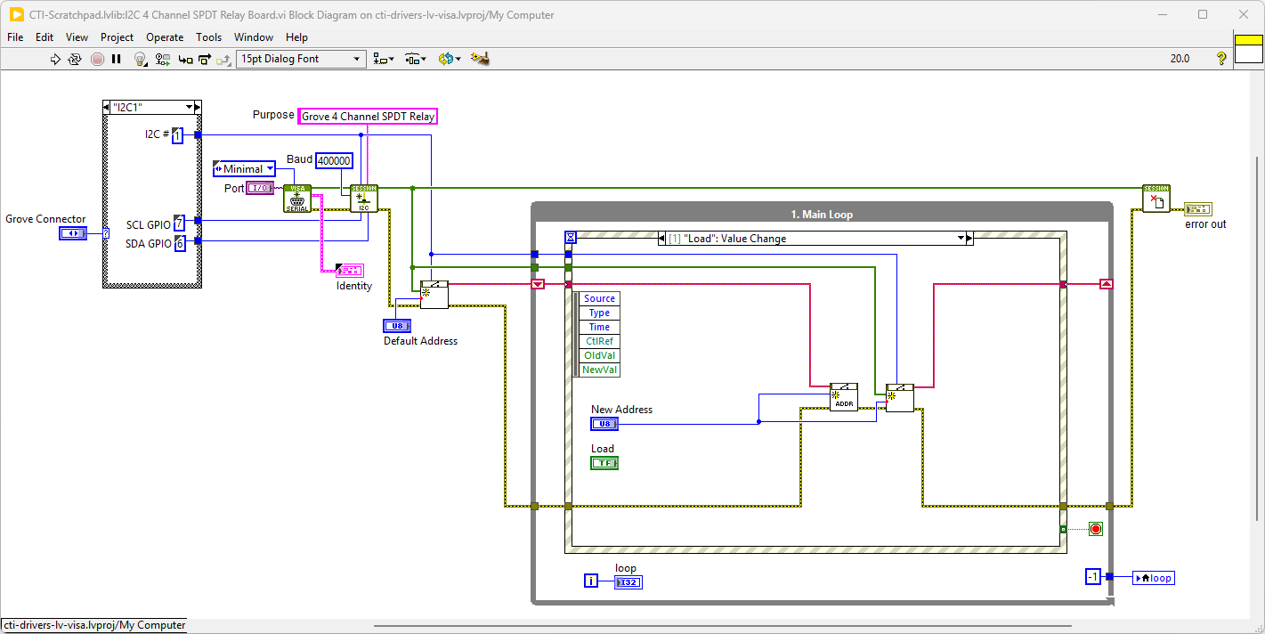
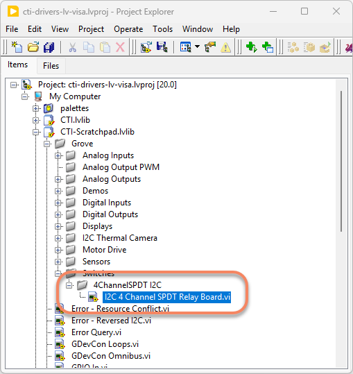
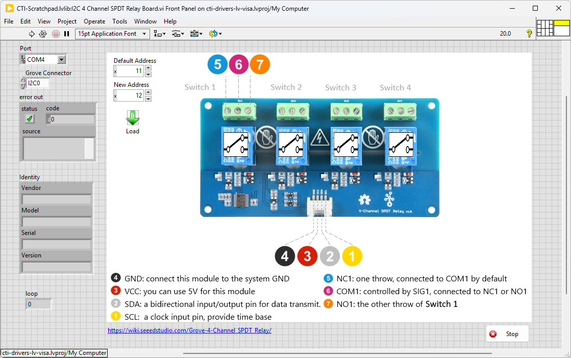
Navigate to >>Scratchpad>>Grove>>Switches>>I2C 4 Channel SPDT Relay Board.vi
This particular VI uses the 4 Channel Relay Board. Select the port for the connected Pico and the Grove connector that the board is plugged into. Press the run arrow.
You can now click on the switch symbols and the corresponding relay will toggle matching the symbol. If you want to change the I2C address for multiple boards, you can modify [New Address] and press the load button. It’s probably a good idea to mark the board with the new address, although it’s fairly easy to ping the addresses of attached modules.
On the block diagram you can see that the selected Grove connector dictates the GPIO Pin for the IC2 Port. We set up the IC2 port for the device in Init.vi. Next we loop round the event structure and wait for a button on the Front Panel to be pressed. When a switch is detected (event:Switch1,Switch2,Switch3 or Switch4) Set Switch.vi recieves the required settings. If the Load button is pressed the new board address is entered and the system re-initialise. Pressing Stop will fire the Stop event and exit the loop.